The kinematics and compliance analysis consists of four force entities:
Name
|
Description
|
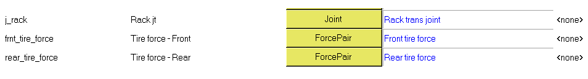
Front Patch Force
|
This is an Action Only force pair applied at the front wheels contact patch with the wheel patch marker as reference to simulate longitudinal, lateral, and aligning forces.
The forces for each direction are defined using expressions as listed below.
|
Fx - Left
|
`SHF(time,60,{ds_knc.max_lon_frc_front.value},0.1*PI,0,0)*
STEP(TIME,60,0,60.01,1)*STEP(TIME,79.9,1,80,0)`
The expression contains a simple harmonic function that applies a sinusoidal force input, whose value is defined in the KnC Parameter DataSet, at a frequency of 0.1PI between 60 to 80 seconds.
|
Fy - Left
|
`SHF(time,20,{ds_knc.max_lat_frc_front.value},0.2*PI,0,0)*
STEP(TIME,20,0,20.01,1)*STEP(TIME,39.9,1,40,0)`
The expression contains a simple harmonic function that applies a sinusoidal force input, whose value is defined in the KnC Parameter DataSet, at a frequency of 0.2PI between 20 to 40 seconds.
|
Fz – Left
|
0
|
Tx – Left
|
0
|
Ty – Left
|
0
|
Tz – Left
|
`SHF(time,40,{ds_knc.max_algn_tor_fr.value},0.2*PI,0,0)*
STEP(TIME,40,0,40.01,1)*STEP(TIME,59.9,1,60,0)`
The expression contains a simple harmonic function that applies a sinusoidal torque input, whose value is defined in the KnC Parameter DataSet, at a frequency of 0.2PI between 40 to 60 seconds.
|
Fx - Right
|
`SHF(time,60,{ds_knc.max_lon_frc_front.value},0.1*PI,0,0)*
STEP(TIME,60,0,60.01,1)*STEP(TIME,79.9,1,80,0)`
The expression contains a simple harmonic function that applies a sinusoidal force input, whose value is defined in the KnC Parameter DataSet, at a frequency of 0.1PI between 60 to 80 seconds.
|
Fy - Right
|
`SHF(time,20,{ds_knc.max_lat_frc_front.value},0.2*PI,0,0)*
STEP(TIME,20,0,20.01,1)*STEP(TIME,29.9,1,30,0)-SHF(time,30,{ds_knc.max_lat_frc_front.value},0.2*PI,0,0)*
STEP(TIME,30,0,30.01,1)*STEP(TIME,39.9,1,40,0)`
The expression contains a simple harmonic function that applies a sinusoidal force input, whose value is defined in the KnC Parameter DataSet, at a frequency of 0.2PI between 20 to 40 seconds. For the first 10 seconds between 20 – 30 seconds, the force is positive Y direction and vice-versa for the next 10 seconds. This is done to simulate parallel and opposing lateral forces with respect to the left wheel.
|
Fz – Right
|
0
|
Tx – Right
|
0
|
Ty – Right
|
0
|
Tz – Right
|
`SHF(time,40,{ds_knc.max_algn_tor_fr.value},0.2*PI,0,0)*
STEP(TIME,40,0,40.01,1)*STEP(TIME,49.9,1,50,0)-SHF(time,50,{ds_knc.max_algn_tor_fr.value},0.2*PI,0,0)*
STEP(TIME,50,0,50.01,1)*STEP(TIME,59.9,1,60,0)`
The expression contains a simple harmonic function that applies a sinusoidal torque input, whose value is defined in the KnC Parameter DataSet, at a frequency of 0.2PI between 40 to 60 seconds. For the first 10 seconds between 40 – 50 seconds, the torque is in the same direction as the left wheel and opposite to it for the next 10 seconds. This is done to simulate parallel and opposing aligning torques with respect to the left wheel.
|
Rear Patch Force
|
This is an Action Only force pair applied at the rear wheels contact patch with the wheel patch marker as reference to simulate longitudinal, lateral and aligning forces.
The forces for each direction are defined using expressions as listed below.
|
Fx - Left
|
`SHF(time,60,{ds_knc.max_lon_frc_front.value},0.1*PI,0,0)*
STEP(TIME,60,0,60.01,1)*STEP(TIME,79.9,1,80,0)`
The expression contains a simple harmonic function that applies a sinusoidal force input, whose value is defined in the KnC Parameter DataSet, at a frequency of 0.1PI between 60 to 80 seconds.
|
Fy - Left
|
`SHF(time,20,{ds_knc.max_lat_frc_front.value},0.2*PI,0,0)*
STEP(TIME,20,0,20.01,1)*STEP(TIME,39.9,1,40,0)`
The expression contains a simple harmonic function that applies a sinusoidal force input, whose value is defined in the KnC Parameter DataSet, at a frequency of 0.2PI between 20 to 40 seconds.
|
Fz – Left
|
0
|
Tx – Left
|
0
|
Ty – Left
|
0
|
Tz – Left
|
`SHF(time,40,{ds_knc.max_algn_tor_fr.value},0.2*PI,0,0)*
STEP(TIME,40,0,40.01,1)*STEP(TIME,59.9,1,60,0)`
The expression contains a simple harmonic function that applies a sinusoidal torque input, whose value is defined in the KnC Parameter DataSet, at a frequency of 0.2PI between 40 to 60 seconds.
|
Fx - Right
|
`SHF(time,60,{ds_knc.max_lon_frc_front.value},0.1*PI,0,0)*
STEP(TIME,60,0,60.01,1)*STEP(TIME,79.9,1,80,0)`
The expression contains a simple harmonic function that applies a sinusoidal force input, whose value is defined in the KnC Parameter DataSet, at a frequency of 0.1PI between 60 to 80 seconds.
|
Fy - Right
|
`SHF(time,20,{ds_knc.max_lat_frc_front.value},0.2*PI,0,0)*
STEP(TIME,20,0,20.01,1)*STEP(TIME,29.9,1,30,0)-SHF(time,30,{ds_knc.max_lat_frc_front.value},0.2*PI,0,0)*
STEP(TIME,30,0,30.01,1)*STEP(TIME,39.9,1,40,0)`
The expression contains a simple harmonic function that applies a sinusoidal force input, whose value is defined in the KnC Parameter DataSet, at a frequency of 0.2PI between 20 to 40 seconds. For the first 10 seconds between 20 – 30 seconds, the force is positive Y direction and vice versa for the next 10 seconds. This is done to simulate parallel and opposing lateral forces with respect to the left wheel.
|
Fz – Right
|
0
|
Tx – Right
|
0
|
Ty – Right
|
0
|
Tz – Right
|
`SHF(time,40,{ds_knc.max_algn_tor_fr.value},0.2*PI,0,0)*
STEP(TIME,40,0,40.01,1)*STEP(TIME,49.9,1,50,0)-SHF(time,50,{ds_knc.max_algn_tor_fr.value},0.2*PI,0,0)*
STEP(TIME,50,0,50.01,1)*STEP(TIME,59.9,1,60,0)`
The expression contains a simple harmonic function that applies a sinusoidal torque input, whose value is defined in the KnC Parameter DataSet, at a frequency of 0.2PI between 40 to 60 seconds. For the first 10 seconds between 40 – 50 seconds, the torque is in the same direction as the left wheel and opposite to it for the next 10 seconds. This is done to simulate parallel and opposing aligning torques with respect to the left wheel.
|
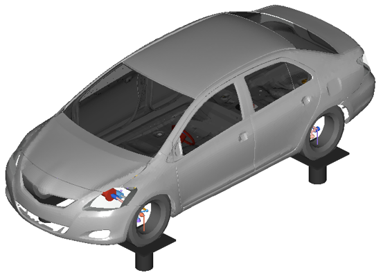
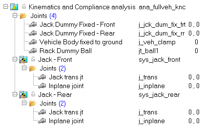
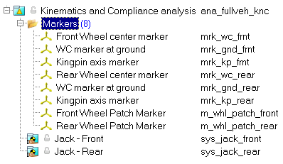
Jack Actuation - Front
|
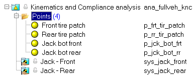
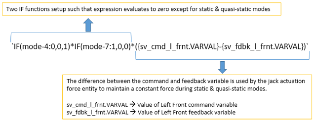
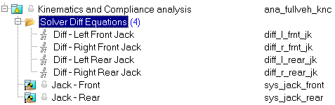
This is an ActionReaction force pair which acts on the jack and is reacted on ground in the vertical direction. The force is a DIF() that points to the SolverDiff ID’s for the Left Front jack and Right Front Jack for the left and right respectively.
When the DIF is evaluated during statics and quasi-statics, the derivative of the Solver Differential Equation is set to zero. The result is that a Force is generated by the DIF that forces the measured wheel displacement to follow the command wheel displacement.
|
Jack Actuation - Rear
|
This is an ActionReaction force pair which acts on the jack and is reacted on ground in the vertical direction. The force is a DIF() that points to the SolverDiff ID’s for the Left Rear jack and Right Rear Jack for the left and right respectively.
|
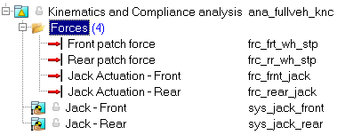
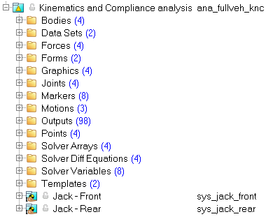
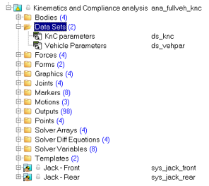
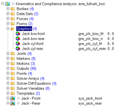
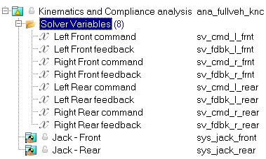
Project Browser View - Forces - Kinematics and Compliance
|