The Dummy Positioning Process Manager is a tool that guides you through a workflow of positioning a dummy in a seat. The recommended steps include an interactive positioning process, during which you specify the H-point position of the dummy, as well as the rotation angles of each joint (arm, leg, and so on.). When finished with this phase, you will be able to store a transformation file which can later be applied on the dummy only in the next phase, the automatic positioning process. In this phase, you can choose to export only the nodes, which creates a copy of the original dummy file with the updated nodes. The rest of the dummy input file remains unchanged with this option.
In the ProcessManager tab, you will see the workflow process. As you complete the positioning process, the boxes will become filled with green checkmarks to indicate the completion of each step.
The H-Point subpanel allows you to position the dummy to the H-Point or rotate the entire dummy about the H-Point. For positioning, you can specify either the coordinates or a node for the new H-Point. For rotating, specify the axis of rotation and the angle. In either case, picking any component in the dummy is sufficient.
The incremental subpanel allows you to rotate an assembly about the coordinate system specified in the tree structure. In this panel, you have an option to rotate about the child or the parent system. The min stop and max stop angles for the x, y, z, axis associated with the joint are retrieved from the dummy database. When the minimum and maximum angles are reached, the assembly is not allowed to rotate any further.
| Note: | Do not use the Rotate panel in the Tools panel to rotate the dummy. Doing so corrupts the tree structure and produces incorrect results when you reposition the dummy. |
|
Process:
| 1. | In the Abaqus Explicit template, open the Utility menu and click the button PositioningProcess. |
| 2. | Click Create/Open to start a new ProcessManager instance. |
| 3. | In the panel area, select the Interactive positioning radio button and select Apply. |
| 4. | Click the file browser icon to browse for the dummy input file (*.inp) to open. |
| 5. | In the Positioner filename field, browse for the *.pos file to load. When both files are established, click the Load button. You can change the default settings for the import options as needed. Default settings include using free format import and preserving include files upon import. |
| Note: | The Import Process Message dialog box may appear. If it does, click Close the dialog and continue the process. If you are intending to exchange only the nodal coordinates of the dummy file at the end of the process, eventually reported unsupported cards do not require action in this case |
|
| 6. | In the next panel, use the browse button to select the non-dummy files, such as the seat. If you have more than one file to load, click the Add button to display more fields. Click Load to load the file(s). |
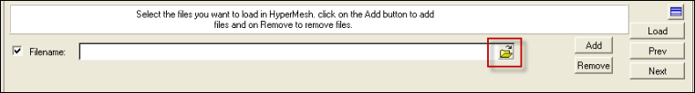
Use the Load File icon to browse for the file to open
| 7. | After the files are loaded, click on the H-point subpanel and position the dummy in the H-Point using the fields available. Click the comps button and select the dummy graphically. Enter the coordinates to position the model and rotate as needed. |
| 8. | Once the dummy is positioned in the H-point, click on the Incremental subpanel. Make your changes and click return. |
| 9. | In the next panel, you can visualize the stop angles (lower/upper/current) for the elements used in the dummy. Click the Show Plot button to display the plot in the graphics area. Click Next to move to the next panel. |
| 10. | The transformation file is now created. This is needed to automatically position the dummy later when no other file (such as the seat) is loaded. In the field, enter a name and folder location and click Create. |
| 11. | In the Create documentation panel, you can create an HTML report that lists the document angles and positions of the dummy, as well as screen shots of the model. Enter a name and location for the HTML document and click Create. |
| 12. | In the ExportFiles steps, select whether to export the model or save it as an HM file. You can also choose to skip this task and export the dummy later, during the automatic process. Click Export to export the model, or click Next to skip the step. |
| 13. | The AutomaticPositioning phase now begins. In this panel, the files entered at the beginning of the InteractivePositioning process are already filled in the fields. Click Load to load the files into Engineering Solutions. Click OK to delete the current model. |
| Note: | The Import Process Message dialog box may appear. If it does, click Close the dialog and continue the process. If you are intending to exchange only the nodal coordinates of the dummy file at the end of the process, eventually reported unsupported cards do not require action in this case. |
|
| 14. | The Transformation filename is automatically loaded in the panel. Click Execute. |
| 15. | Similarly to the InteractivePositioning phase, you can create an HTML document with the model specifics. Click Create, or click Next to skip the documentation task. |
| 16. | The last task is to export the dummy solver format or create an Engineering Solutions file. If exporting in solver format, the recommended setting is to select exchange only nodes. This will copy the original dummy file to a new one that uses a name you specified, and will exchange the node positions. You’ll find a comment in front of and after the node block to highlight the exchanged nodes. |
The comments are:
** Begin replaced node block by dummy positioning tool
** End replaced node block by dummy positioning tool"
The ProcessManager tree should now be completed, with each task showing a green checkmark.


