|
»Click here to display Table of Contents«
|

Acoustic Cavity Tab |

|

|

|

|
|
Acoustic Cavity Tab |
|
|
|

|
|
»Click here to display Table of Contents«
|
Acoustic Cavity Tab |
|
|
|
|
|
Acoustic Cavity Tab |
|
|
|
|
Once a preview mesh is created in the Acoustic Cavity Mesh panel, the AcousticCavity tab is populated with each cavity mesh that is generated. In this tab, define element quality criteria and select individual volumes for refinement into final, computational volume meshes.
The following buttons are available in the Acoustic Cavity tab:
Button |
Action |
||||||||||||||
|
Opens the Options dialog, from which you can define settings for creating acoustic cavity mesh.
|
||||||||||||||
|
Perform a rerun preview. This tool is helpful if you change the element quality criteria or similar settings in the Options dialog, or alter the mesh type or response points. |
||||||||||||||
|
Opens the Interface dialog, from which you can create and review interfaces between structural and created acoustic cavity components.
|
||||||||||||||
|
Opens the Create MPCs dialog, from which you can create MPCs between selected acoustic cavity components. MPCs can be created between selected components. It is possible to select Fluid, Structure, and Patch components and set them as Master and Slave to create MPCs between them accordingly. There are options to select grids for creating MPCs within a specified tolerance. MPCs are typically created between fluid components, except for cases where there are BIOT material components, identified as structural components, which can also be coupled to fluid components. MPCs are created by coupling each face node (dependent node) on the slave component to all face nodes within the specified tolerance on the master component (independent nodes). When two cavities being coupled are separated by patch elements or structure components, MPCs can be created for face grids through patch hole only, or face grids NOT through patch hole, instead of all face grids. |
||||||||||||||
|
Isolates acoustic cavities, and hides all of the geometry and mesh in the model. |
||||||||||||||
|
Displays cavities, along with the body elements that were used to generate them. |
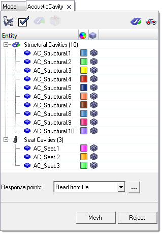
The tree displays each cavity mesh generated (up to the limit, if any, specified in the Options window). The cavities are segregated into separate groups for Structural Cavities, such as air spaces, and Seat Cavities, which are modeled as self-contained internal cavities. Each cavity has view options controlled in a fashion similar to the Model browser. A check box lets you choose whether or not to obtain a computational mesh for the cavity; right-clicking the color box lets you change the color that each cavity displays in; and right-clicking the mesh type icon lets you to pick between several display options: wireframe, solid, solid with feature lines, solid with mesh lines (which is the default), and semitransparent.
In addition, right-clicking a cavity brings up options to rename it, show/hide/isolate/isolate only, expand or collapse the tree nodes, change which columns display in the browser, or access the Acoustic Cavity tab's Options window.
Use the collection of list boxes and command buttons at the bottom of the tab to create the computational mesh from a preview mesh, or to remesh an existing cavity.
| • | Response points. response points can be used to specify test microphone locations (usually to simulate the passenger's ears). Pick nodes in the model to be the response points, or load them from an existing file. |
If you choose Read from file, use the browse button to locate and select the file containing response points. Such files must be in the proper format, and should be comma-separate value (CSV) files. The image below shows an example of the format.
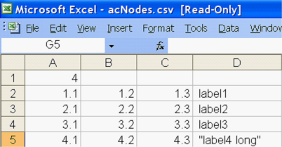
In this example, A1 is the number of response points (4); rows 2-5 contain the X, Y, and Z coordinates of each point, ending with the point's name in column D.
| • | Mesh. Generates a new, computational mesh based on the mesh type and options defined. |
If the initial mesh is unacceptable due to quality requirements, response point placement, mesh type, or any other setting that originates from the AcousticCavity tab (rather than the Acoustic Cavity Mesh panel), use the Rerun Preview tool (![]() ) to create a new preview using the updated settings. Do not click Reject, as this will reject the preview as well as the computational mesh, and will close the tab.
) to create a new preview using the updated settings. Do not click Reject, as this will reject the preview as well as the computational mesh, and will close the tab.
Pause the meshing process by clicking and holding the right mouse button. A dialog opens, asking if you wish to stop the meshing; if you choose yes, the mesh will be only partially generated and quality will most likely suffer.
| • | Reject. Rejects the mesh completely, including the preview mesh, and closes the tab. |
| Note: | As long as the Acoustic Cavity Mesh panel is open when you reject, your original input repopulates the component and seat collectors. This allows you to quickly change one or two settings, such as mesh or patch sizes, and then regenerate a preview without having to reselect all of the relevant components. If you exit the panel and then click reject, returning to the panel will not restore your previously chosen entities. |
When you Reject the mesh, the components labeled ac_structural and ac_seats (which are created when the preview mesh is generated) are deleted. On a case-by-case basis, you can retain these by renaming them before you reject the mesh.
| • | Close. Closes the tab, but retains the current cavity meshes. This also clears all input from the Acoustic Cavity Mesh panel. |