|
»Click here to display Table of Contents«
|

ANSYS Connector Types |

|

|

|

|
|
ANSYS Connector Types |
|
|
|

|
|
»Click here to display Table of Contents«
|
ANSYS Connector Types |
|
|
|
|
|
ANSYS Connector Types |
|
|
|
|
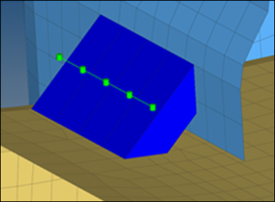
CFG ansys 105 hexa (tapered T) *filter seam *style continuous 6 *head *body 0 hex8 1 1 |
|
Description: Intended to be used for t-cases. The size and exact position can be defined thickness dependent, or the exact dimension and position parameters can be given. |
|
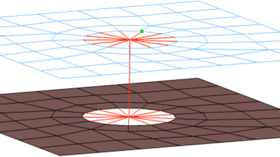
CFG ansys 112 bolt *filter bolt *style bolt 0 *head rigid 1 1 *body 0 rod 2 1 *post prop_ansys.tcl |
|
Description: Creates a body with element type ‘Link10’ element. CERIG elements will be created at the head. Head elements project and connect to the adjoining elements that form the hole. Properties and materials for the Link10 element are also created. |
|
CFG ansys 113 bolt (BEAM44) *filter bolt *style bolt 0 *head rigid 1 1 *body 0 bar2 7 1 *post prop_ansys.tcl
|
|
Description: Creates a body with element type ‘Beam44’ element. CERIG elements will be created at the head. Head elements project and connect to the nodes of adjoining elements that form the hole. Properties and materials for the Beam44 element are also created. |
|
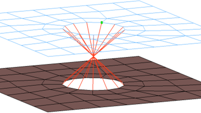
CFG ansys 114 clip *filter bolt *style bolt 1 *head *body 0 rigidlink 1 2 *post prop_ansys.tcl
|
|
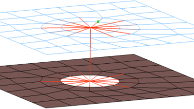
Description: Creates CERIG and Mass21 elements. Mass21 element is created at the center location of bolt body. CERIG elements connect Mass21 to the nodes of adjoining elements of the shell that form hole. CERIG elements, from Mass21 also connect to the nodes of the element that represent the washer of the bolt. Properties and materials are also created for the Mass21 element type. The connector location can either be on the edge of the hole, center of the hole, midpoint in between the two holes, or on the second row of nodes which form the washer layer. |
|
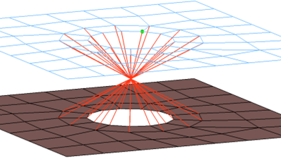
CFG ansys 115 bolt (spider) *filter bolt *style bolt 1 *head *body 0 rigid 1 1 *post prop_ansys.tcl
|
|
Description: Creates many individual CERIG elements. The element projects and connects to the nodes of the adjoining shell elements which form the hole, the CERIG elements are joined at the midpoint of the bolted connection. A MASS21 element is created at this location. The connector location can either be on the edge of the hole, center of the hole, midpoint in between the two holes or on the second row of nodes which form the washer layer. Properties and materials for the MASS21 element is also created. |
|
CFG ansys 116 bolt (washer 1) *filter bolt *style bolt 0 *head rigidlink 1 12 *body 0 rod 2 1 *post prop_ansys.tcl |
|
Description: Creates CERIG element for the head and LINK10 for body. The head elements project and connect to the nodes of the adjoining shell elements which form the hole and also the second row of nodes which form the washer layer. The connector location can either be on the edge of the hole, center of the hole, midpoint in between the two holes or on the second row of nodes which form the washer layer. Properties and materials are also created for the LINK10 element. |
|
CFG ansys 117 bolt (washer 1 alt) LINK10 *filter bolt *style bolt 0 *head rigidlink 1 13 *body 0 rod 2 1 *post prop_ansys.tcl |
|
Description: Creates CERIG element for the head and LINK10 element for body. The head elements project and connect to the nodes of the adjoining shell elements which form the hole and also the second row of nodes which form the washer layer. The head only connects to every other node on the washer layer. The connector location can either be on the edge of the hole, center of the hole, midpoint in between the two holes or on the second row of nodes which form the washer layer. Properties and materials are also created for the LINK10 element. |
|
CFG ansys 118 bolt (washer 1) BEAM44 *filter bolt *style bolt 0 *head rigidlink 1 12 *body 0 bar2 7 1 *post prop_ansys.tcl
|
|
Description: Creates CERIG elements for the head and BEAM44 element for the body. The head elements project and connect to the nodes of the adjoining shell elements which form the hole and also the second row of nodes which form the washer layer. The connector location can either be on the edge of the hole, center of the hole, midpoint in between the two holes or on the second row of nodes which form the washer layer. Property and material cards for the BEAM44 element are created. |
|
CFG ansys 119 bolt (washer 2) LINK10 *filter bolt *style bolt 0 *head rigidlink 1 1 rigidlink 1 2 *body 0 rod 2 1 *post prop_ansys.tcl
|
|
Description: Creates CERIG elements for the head and the LINK10 element for body. There are two individual CERIG elements at the head of the connection, one to connect to the inner row of nodes, the other to connect to the washer layer nodes. The connector location can either be on the edge of the hole, center of the hole, midpoint in between the two holes or on the second row of nodes which form the washer layer. Property and material cards are created for the LINK10 element. |
|
CFG ansys 120 bolt (washer 2 alt) LINK10 *filter bolt *style bolt 0 *head rigidlink 1 1 rigidlink 1 3 *body 0 rod 2 1 *post prop_ansys.tcl
|
|
Description: Creates CERIG elements for the head and the LINK10 element for body. There are two individual CERIG elements at the head of the connection, one to connect to the inner row of nodes, the other to connect to the washer layer nodes. The CERIG head element that connects to the washer layer nodes only connects to every other node on the washer layer. The connector location can either be on the edge of the hole, center of the hole, midpoint in between the two holes or on the second row of nodes which form the washer layer. Property and material cards are created for the LINK10 element. |
|