Locations: Tools menu > Pretension Bolt
Use the ANSYS Pretension Bolt utility to create pretension loads in 1D and 3D bolts of ANSYS models using the ANSYS PRETS179 element type. Element PRETS179 is a bar element with a third node used for pre-loading. Using this utility, you can get a pre-loaded bolt with PRETS179 elements created at the desired location with a third node. A pretension section is created and associated with the pretension elements created. Also, the pretension load card SLOAD is created with the defined load in the utility, as well as a load steps on and off values. You can edit this load card after completing this process.
| 1. | From the menu bar, click Preferences > User Profiles. |
| 2. | In the User Profiles dialog, select ANSYS. |
| 3. | From the menu bar, click Tools > Pretension Bolt. |
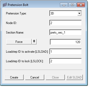
| 4. | In the Pretension Bolt dialog, set the Pretension Type to 3D. |
| 5. | In the Node ID field, enter the node ID for the third node of the pretension element. |
| Note: | If you do not enter a node ID, a default node number will be assigned. |
| 6. | In the Section Name field, enter a name for the pretension section to be created. |
| Note: | If you do not enter a section name, a default name will be assigned. |
| 7. | Toggle the type of method for loading the bolt to either Force or Displacement, then enter a corresponding value. |
| 8. | In the Loadstep ID to activate [LSLOAD] field, enter the load step ID to which the load is to be applied. |
| 9. | In the Loadstep ID to lock [LSLOCK] field, enter the load step ID to which the displacements or force loads needs to be locked. |
| 11. | In the panel area, use the Comps selector to select the bolt component. |
| Note: | Multiple components are not allowed to be selected. If more than one bolt is selected, they will all be placed under one component. |
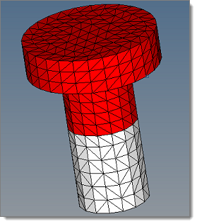
| 13. | Use the elems selector to select the elements which form the cut section of the bolt. Pretension elements are created at this section. |
A typical section is illustrated in the image below.
| 15. | Use the node selector to select two or three nodes that define the load direction for the pretension load. |
| 16. | Click proceed. PRETS179 elements are created at the cut section with the pretension section created and associated to these elements. A SLOAD card with the given pretension load is also created. |
| 17. | To edit the SLOAD card, click Edit SLOAD. |
|
| 1. | From the menu bar, click Preferences > User Profiles. |
| 2. | In the User Profiles dialog, select ANSYS. |
| 3. | From the menu bar, click Tools > Pretension Bolt. |
| 4. | In the Pretension Bolt dialog, set the Pretension Type to 1D. |
| 5. | In the Node ID field, enter the node ID for the third node of the pretension element. |
| Note: | If you do not enter a node ID, a default node number will be assigned. |
| 6. | In the Section Name field, enter a name for the pretension section to be created. |
| Note: | If you do not enter a section name, a default name will be assigned. |
| 7. | Toggle the type of method for loading the bolt to either Force or Displacement then enter a corresponding value. |
| 8. | In the Loadstep ID to activate [LSLOAD] field, enter the load step ID to which the load is to be applied. |
| 9. | In the Loadstep ID to lock [LSLOCK] field, enter the load step ID to which the displacements or force loads needs to be locked. |
| 11. | In the panel area, use the Nodes selector to select the nodes of the 1D elements where the pretension element needs to be created. |
| 12. | Click proceed. PRETS179 elements are created at the node locations, with the pretension section created and associated to these elements. A SLOAD card with the given pretension load is also created. |
| 13. | To edit the SLOAD card, click Edit SLOAD. |
|


