You can create 2D and 3D contact pairs with the Surface to Surface and Point to Surface options. You can also define contacts using the Pilot Node option.
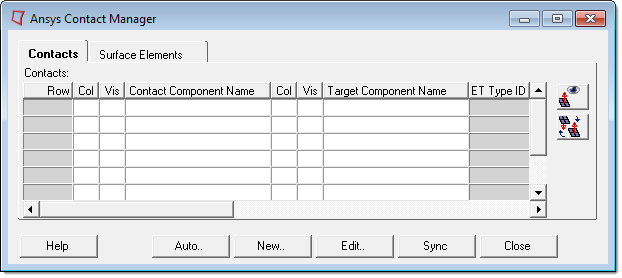
| 1. | From the Utility menu, click Contact Manager. The Ansys Contact Manager opens and the Contact tab is displayed by default. |
| 2. | Click New to create a new contact pair. The Create New Contact Pair dialog opens. |
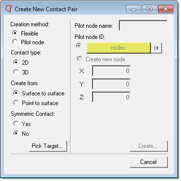
| 3. | Under Creation method, select Flexible or Pilot node. |
| 4. | In the Contact type field, select 2D or 3D. |
| 5. | Under Create from, select whether to create a surface to surface contact pair or a point to surface contact pair. |
| 6. | Under Symmetric Contact, select Yes or No. |
To create two pairs of symmetry contacts, click Yes. In order to create a symmetry pair, the selected elements must meet all of the element configuration requirements.
| • | Contact elements in the first pair will be target elements in the second pair. |
| • | Target elements in first pair will be contact elements in the second pair. |
| • | Different properties and ET types will be created for the second pair. You can update the contact pair with desired properties and contact options later. |
| 7. | Click Pick Target to select the target body components. |
| 8. | From the panel area, click the comps selector. |
| 9. | Select the components that belong to the target component elements. |
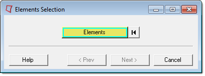
| 12. | In the Target Elements Selection dialog, click the Elements selector. |
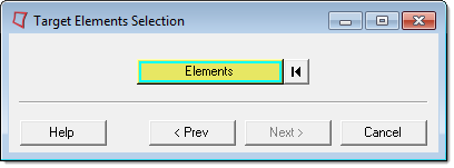
| 13. | In the panel area, verify that the elems selector is active, then select the target elements of the contact pair. |
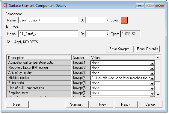
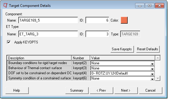
| 15. | In the Target Elements Selection dialog, click Next. The Target Component Details dialog opens. |
This dialog displays a default name and color for the target component, which can both be modified. You can also modify the ET Type name and the ID of the target component, as well as the values of the key options. Once Save Keyopts is clicked, all of your changes will be applied to the target element. The next time you create a new contact pair, the options you selected in the dialog will be saved and you will not need to apply them again.
| 17. | In the Contact Components Selection dialog, click the Components selector. |
| 18. | In the panel area, click the comps selector. |
| 19. | Select the components to assign as the target body. |
| 23. | In the Select Contact Elements dialog, click the Elements selector. |
| 24. | In the panel area, verify that the elems selector is active, then select the elements to assign as the contact surface elements. |
| 26. | Click Next. The Contact Component Details dialog opens. |
This dialog displays a default name and color for the contact component, which can be modified if desired. The ET type and the ID of the contact component can also be modified.
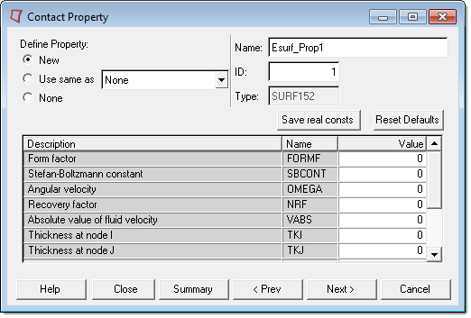
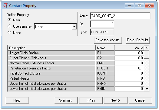
| 28. | In the Contact Property dialog, enter the values for items shown. You can create a new property, or create a new one based on an existing property, which helps expedite the process. Click Save real constants to save the property values you entered. In the future, when the Contact Property dialog opens, the values you saved will appear by default. |
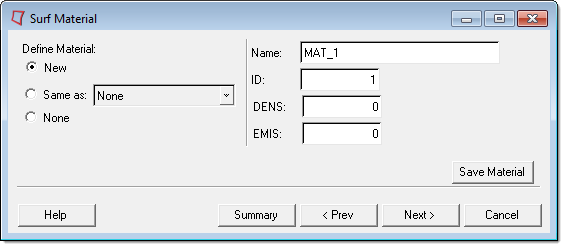
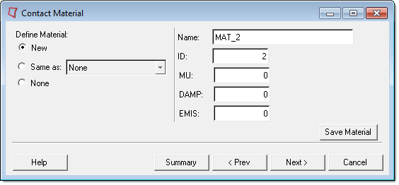
| 30. | In the Contact Material dialog, click New to define a new material or select None to skip defining a material. |
| 31. | Click Next. The Ansys Contact Manager dialog opens and displays a summary of the target and contact elements. The contact pair you created is displayed. |
| 32. | To exit the Contact Manager, click Close. |
| 33. | To repeat this process, click Restart. |
|