This panel helps you isolate holes based on diameter ranges. Isolating and meshing holes separately from other geometry features is a very important step during tetra meshing; failing to do so can drastically affect the overall mesh quality. You may also wish to use this step even when there are no specific meshing requirements for holes just to organize your model.
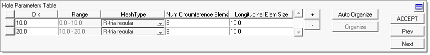
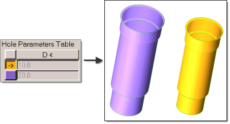
Much of the functionality in this panel comes in the form of a table; individual cells within the table are a mix of display-only information and entry fields. Once organized, each table row has a color button on its left which corresponds to the Engineering Solutions component holding hole surfaces. Clicking one of these buttons selects the entire row, making it the "active" row. To deselect an active row, click the colorless button at the very top-left corner of the table (the one in the header row along with the column names).
Use the following entry fields in the active columns to specify how holes are located and meshed:
Entry Field
|
Description
|
D <
|
The tool automatically selects holes with diameters of less than the value you specify. If you add multiple lines to the table, Engineering Solutions generates non-overlapping ranges from them.
| Note: | If you have no specific requirements for hole meshing, you can use a single diameter value that is larger than the largest holes in the model, in order to select all of the holes. |
|
Num Circumference Elems
|
This determines the number of elements that you wish placed around the circumference of any holes of the specified diameter range. Higher numbers result in a smoother mesh that better approximates a hole's shape and curvature, but could impact tetramesh quality if they result in smaller elements around the hole's edges than the enforced element size for other surfaces. If you have no specific requirements for hole meshing, Altair recommends using at least 6 elements for each hole's circumference.
|
Longitudinal Elem Size
|
The desired element size in the longitudinal direction--that is, traveling along the depth of the hole. If you have no specific requirements for hole meshing, it is best to use the same element size as the rest of the model.
|
Add or Remove rows
(+ and - buttons)
|
Use the (+) button to add another row to the table if you require multiple sets of hole criteria. Conversely, you can remove the active row with the (-) button to remove unneeded criteria sets.
| Note: | There is no way to undo the removal of a row! If you accidentally remove the wrong row, you will need to add a new row and recreate it. |
|
Auto Organize
|
This automatically organizes the holes into separate components based on the input parameters (diameter, etc.), so you get one component for each row in the table and the holes are placed into the components that their diameter and other criteria match. The model holes (and corresponding table rows) are color-coded according to the component that they have been sorted into.
|
Organize
|
Opens the Organize panel, from which you can manually organize any holes that were missed by the Auto-Organize routine into components.
| Note: | This option only becomes available after using Auto-Organize. |
|
Click Prev to return to the Geometry Cleanup panel, or click Next to continue. You can also click on a specific task in the Process Manager to go to the appropriate panel.


