Connector Realization |

|

|

|

|
|
Connector Realization |

|

|

|

|
During connector realization, welds are created using the connector definition.
|
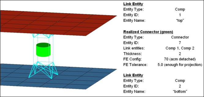
The following diagram shows connector seven realized with a valid tolerance value, and a config value of type 70 (acm detached).

One advantage of separating weld FE realization from the connector definition is that a connector can be re-realized as a weld of a different configuration (or possibly, a user-defined weld) without having to redefine the connector. If you edit the connector definition (for example, add or delete a link entity from the connector), the connector removes the welds it created, and reverts back to an unrealized state. The connector is unrealized only if its user-control mode is turned off. By default, the connector mode is off but it can be turned on by registering custom FE with a connector. Connectors store all FE information that they create, allowing advanced find, mask, delete, and organizational functionality in a number of common panels. If the weld creation is unsuccessful (due to low tolerance, insufficient link entities, etc.) the connector icon is displayed as failed (red). An unrealized connector is yellow, a realized connector is green, and a failed connector is red.
Connectors are realized at creation or later, on the appropriate connector panel. See Realization Types by Panel in Connector Panels for details.