|
»Click here to display Table of Contents«
|

Element Cleanup |

|

|

|

|
|
Element Cleanup |
|
|
|

|
|
»Click here to display Table of Contents«
|
Element Cleanup |
|
|
|
|
|
Element Cleanup |
|
|
|
|
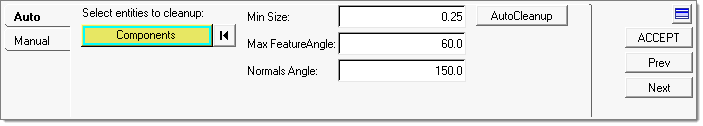
This stage in the process focuses on optimizing the quality of the elements created during each of the previous meshing stages. The panel includes two tabs: one for automated cleanup, and one for manual cleanup.
From this stage, clicking ACCEPT or Next continues to the Tetramesh panel. Clicking Prev returns to the Global Mesh stage.
The AutoCleanup tab includes controls to specify the minimum size that is acceptable for any given element, the maximum feature angle that will be preserved, and the Normals Angle.
|
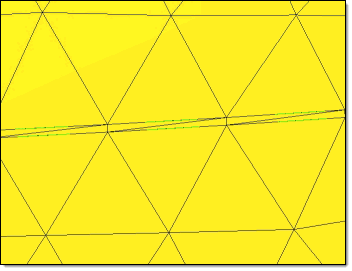
Minimum feature angle (low value) |
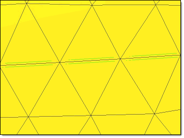
Minimum feature angle (high value) |
In addition, the Normals Angle specifies the maximum allowable angle between the normals of adjacent elements. When possible, adjacent elements whose normals exceed this angle will be split into multiple smaller elements with less-extreme normal angles.
When you click the AutoCleanup button, the mesh is examined within each component individually, removing elements of poor quality and stitching the mesh together to fill the resulting gaps. Cleaning up the mesh on a per-component basis prevents mesh overlap between adjacent surfaces that belong to different components.
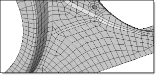
Before Element Cleanup – note "sliver" elements along midline |
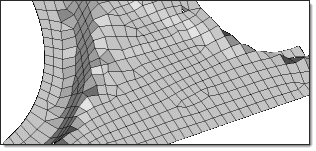
After Element Cleanup – small / sliver elements are removed |
This tab includes a toggle to choose between finding Free edges (which are associated with only 1 surface) and T-connections (which are associated with three edges) and a button to perform the Find. In addition, another button is available to Display Normals as vectors in the graphics area.
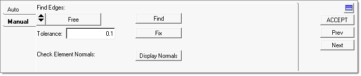
After you find edges, you can choose to clean them using specific Tolerance value. Engineering Solutions will use this tolerance value identify nodes associated with free edges and try to stitch them, leaving nodes outside the tolerance unchanged. Click on Fix to fix free edges.
Clicking Display Normals opens the Normals panel. Completing it returns to the Manual Cleanup tab.
Once you have finished with mesh cleanup, and all of the relevant previous stages are complete, clicking ACCEPT or Next continues to the Tetramesh panel, where you can generate the 3D mesh from the existing surface meshes.
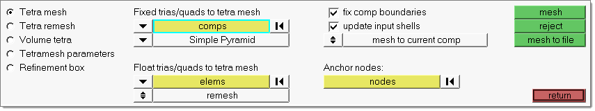
For instructions on using the Tetramesh panel, refer to its specific panel help.
|
You can also click on a specific task in the Process Manager to backtrack to the appropriate panel.