| 1. | Use the FBD type selector to determine the grid point force and moment data to extract and utilize for FBD calculations for each node in the selected element set. Available options include All Loads, Applied Loads Only, and Reaction Loads Only. |
| • | All Loads extracts and utilizes all element contribution, applied, SPC, and supported MPC grid point data for FBD calculations on the nodes in the selected element set. |
| • | Applied Loads Only extracts and utilizes only the applied loads grid point data for FBD calculations on the nodes in the selected element set. |
| • | Reaction Loads Only extracts and utilizes only SPC and supported MPC grid point data for FBD calculations on nodes in the selected set. |
MPC force and moment data are properly extracted for the following MPC constraint types: RBE2, RBE3, Rigidlink, RJOINT, RROD, and RBAR.
| 2. | Use the Zero Tolerance entry field to define the cut-off point below which a result quantity is considered zero. |
All calculations are performed with floating point precision and the zero tolerance value is only used to control the output of results to the various formats. This option helps to prevent relatively small values from being output to the result formats. To maintain floating-point precision the default is set to 1.0e-6; modify the value as desired.
| 3. | Use the Create Load Collectors option to extract the specified grid point data and display it in organized load collectors for visualization in the model window. |
Multiple load collectors are created — one for each force and moment component — for each selected loadstep of the current element set. The load collector name format is "FBDF_E(#)_S(#)_(compID)". For example FBDF_E(1)_S(1)_Fx would be created for element set 1, loadstep 1, and component Fx. In addition a load collector with the Nastran/OptiStruct LOAD card is also created, referencing the component force and moment load collectors. This load collector is named "FBDF_E(#)_S(#)_C" and can be referenced in the loadstep panel as the LOAD entry for the various loadstep definitions.
| • | The Color option allows you to choose a color for all created load collectors. This color can be modified later using either the interface or the FBD Results Manager utility. |
The FBD Results Manager can be used to review the load collectors generated from FBD Forces utility. When you save the database, all FBD Forces load collectors are saved to the database. This allows FBD information to be reviewed and utilized in the future without having to rerun the tool. Renumbering element or node sets after running the tool invalidates the link between the load collector names and the associated sets; therefore it is important to avoid renumbering any element or node sets for which FBD result must be retained as load collectors in Engineering Solutions.
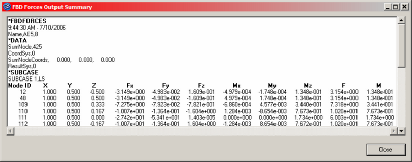
| 4. | To output the results to a popup window for instant review, activate the Show summary table option. |
The table contains information about the loadsteps, element set(s), and detailed data from the grid point extraction at each node. A sample window with partial output is shown below.
| 5. | Use the Create .csv file option to create a .csv file that contains the same information as the summary table, but in a comma-separated file. |
You may select a new file or an existing file. If an existing file is selected, it is appended to, and there are several items to note:
| • | If the data you are extracting already exists in the file (based on element set, loadstep IDs), the existing block will be overwritten with the new data. If it does not exist, it will be appended to the end of the file. |
| • | You are asked if you wish to replace the existing file. However, selecting yes will not overwrite the file — it will append/replace the data as described above. |


