|
»Click here to display Table of Contents«
|

Free Body Diagrams |

|

|

|

|
|
Free Body Diagrams |
|
|
|

|
|
»Click here to display Table of Contents«
|
Free Body Diagrams |
|
|
|
|
|
Free Body Diagrams |
|
|
|
|
You can create or edit Free Body Diagrams (FBD) using several tools that display in the tab area. Each FBD tool displays on a separate tab, which opens when you activate that tool.
Free Body Diagram (FBD) utilities facilitate the extraction and post-processing of grid point force results. FBD extractions are typically utilized for breakout and/or sub-modeling analysis schemes, where balanced "free body" sub-cases are extracted from a coarse grid model and applied to a fine grid sub-model for eventual optimization and/or analysis. FBD is also used to extract cross-sectional resultant forces and moments (typically at the centroid of a cross-section) for use in traditional strength calculations.
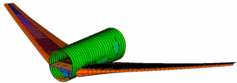
This coarse grid model is typical for FBD extractions
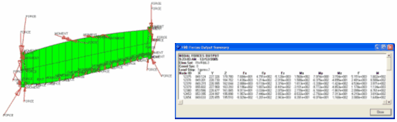
Typical FBD – Forces output on a wing rib
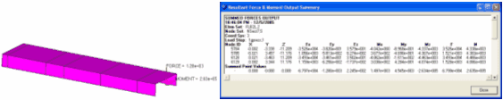
Typical Result Force and Moment output on a floor beam
Each tool has a separate entry in the menu. Click the links below for details on the use of each tool:
See Also:
Free Body Diagrams - Nastran Interfacing
Free Body Diagrams - OptiStruct Interfacing
Grid Point Force Balance tables to gain further understanding of FBD operations
Set Browser utility to assist in generating the element and node sets which the FBD utilities require.