Use the connector Area panel to create connectors that represent connections of larger regions, such as adhesives. These connectors can later be realized as standard or custom weld representations.
| Note: | Whereas the test points on a seam connector are characterized by cylinders along the connector line, the test points of an area connector are characterized by nodes of an internal mesh dedicated to the connector. During connector creation the internal mesh can be created by adopting the mesh used for location, or the defined region is automeshed with a certain mesh type. |
|
When the Area panel is active, only area-type connectors display in the graphics area; graphics for other connector types are suppressed until you exit the panel.
Panel Usage
The Area panel is arranged into several subpanels. You can move freely between subpanels--your work on one subpanel will not be lost if you switch to a different subpanel. Typically one or more green command buttons on the right edge of the subpanel must be used to execute the function once all needed entries and options have been specified.
| • | Set the panel mode by selecting the subpanel appropriate to the command you wish to execute. |
| • | In the subpanel, choose entries and options to characterize new area connectors, or edit existing ones. |
Subpanels
The Area panel contains the following subpanels and command buttons:
| • | Area: Create and realize area connectors in a single process. |
| • | Create: Create, but do not realize, area connectors. |
| • | Realize: An existing Area connector is realized only (no creation or editing possible). |
| • | Edit: An existing Area connector's characteristics are edited. |
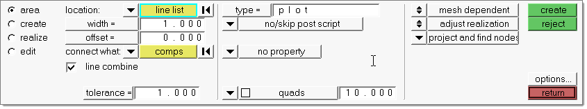
The area, create and realize subpanels use the same set of entry controls. They are organized in three different columns:
| 1. | The first column contains everything related to connector creation and link detection. |
| 2. | The second column contains everything related to realization type, post script and property assignment. |
| 3. | The third column contains everything related to the final connection to the link entities. |
These columns and their organization are illustrated in detail in Connector Panel Structure in the Connectors chapter. See Special Realization Types in the Connectors chapter for further information on specific realization types.
From the Area panel you also have direct access to the Connector Options panel, where general and connector type-specific settings can be set. In particular, settings which don’t need to be altered very often are provided there.
Panel Input
Input
|
Description
|
location
|
Specify the location of the connector to be created by selecting one of the following:
|
The region for the area connector is defined by the selected shell elements. The internal connector mesh is created by adopting the mesh used for location. It is automatically detected if all the selected elements are attached to each other. If this is not the case, one area connector per each element patch is created.
|
|
For each selected surface one area connector is created, even if the surfaces are attached to each other and share the same green edge. The internal connector mesh is created dependent on the defined mesh type and mesh size. See description below.
|
|
Select lines or a line list and specify the mesh type, the width and/or the offset.
If you select several lines, Engineering Solutions determines whether lines share the same start- and end-points or not. This means HyperMesh is able to determine whether several lines form a continuous line. From these lines only one single area connector is created.
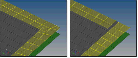
| Note: | There is a limitation for lines with sharp vertices; in such a case the area connector might not provide satisfactory results. The quality depends on the vertex angle on the line, the width and if an offset needs to be done. See the example below: |
The area connector will automatically be oriented parallel to the closest link.
It is recommended to use free lines or free surface edges.
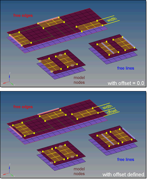
If a free line is selected, then the area connector is created with the defined width centered about it. The offset option is considered only in cases where the selected free line is on a free mesh edge, in which case the behavior is exactly the same as for the free surface edge.
If the offset option is considered with the default of 0.0, the area connector is positioned with its one outline on the free mesh edge, such that the complete connector lays exactly along the free edge but inside the link.
|
|
Select a nodelist and specify the mesh type, the width, and/or the offset. From this nodelist Engineering Solutions internally creates a line, so the behavior of a nodelist is very comparable to a linelist.
With this method only one area connector is ever created.
| Note: | There is a limitation for node lists with sharp vertices; in such a case the area connector might not provide satisfactory results. The quality depends on the vertex angle on the novelist, the width and if an offset needs to be done. See the example above for lines / linelist. |
The area connector will automatically be oriented parallel to the closest link.
It is recommended to use mesh nodes, although temp nodes can be used.
When nodes are selected with the by path option, a check is run to determine if the selected nodes are located along a free mesh edge. If fewer than 3 nodes are on a free mesh edge the area connector is created centered about the selected nodes. If the nodes are on a free edge then one of the edges of the area connector will coincide with the node path (offset = 0.0).
|
|
width
|
Width of the connector area centered along the line. Only available when the location is lines or node list.
|
offset
|
This is the connector is offset from the free mesh edge along the link by this distance. Only available when the location is lines or nodelist.
|
connectors
|
Select the area connector to be realized. Only available in the edit and realize subpanels.
|
line combine
|
This is the default setting when the location is a line list. With this option active, a sequence of lines will be internally treated as on line. One seam connector is created for each sequence of lines and each single line.
This option is preferred for continuous seams together with realization types where the body element is positioned between the weld points like for all quad and hexa seam realizations.
| Note: | With this option, neither the vertices nor the start- and end- points of the initial lines are considered, and there likely won’t be any weld points at the exact positions. |
|
mesh type
|
Select the mesh types the connector should be meshed with. Available mesh types are quads, trias, mixed and R-trias.
| Note: | There is no interactive mesh manipulation available. A few more options can be used during editing an area connector. |
This option does not display when the location is elems.
|
mesh size
|
Specify the mesh size the connector should be meshed with. This option does not display when the location is elems.
|
connect what
|
Select the entities which should become link candidates. Link candidates are certain entities of a chosen Link Type, which are supposed to be connected during the realization. Entities outside the tolerance are not taken into account.
|
Select the components to be added as link entities. You can choose to connect to either the geometry or elements of the selected components.
|
|
Select the assemblies to be added as link entities. You can choose to connect to either the geometry or elements of the selected assemblies.
|
|
Select the surfaces to be added as link entities. You can choose to connect to either the geometric surfaces or elements associated to the selected surfaces.
|
| Note: | Connectors can be created with different types of entities; for example, a connector can be defined by selecting a component on one side and an assembly on the other side. This can be done by creating an area connector to specify one of the entity types and selecting that entity. Add the second entity by updating the connector via the add links functionality in the Connector browser or the add links panel. |
|
num layers
|
Defines how many thicknesses (layers) have to be connected at the connector position. This number is predefined as two for areas, so there is not any field in the area panel where you can set the number of layers. However, you can find the number of layers for area connectors in the Connector browser.
When the link detection is performed the valid connector links are established with respect to the given tolerance and the selected link candidates. The links are reduced to the minimum needed ones. Often for areas the number of links is higher than the number of layers, because a valid pair of projections need to be found for each test point.
|
tolerance
|
Defines an acceptable distance from the connector location (per test point). Only entities within this tolerance can be taken into account for the link detection and the final realization. Thus, the tolerance is used twice: first for the link determination and again for the realization. In the second step the tolerance is used to verify whether adequate link candidates are available to be connected.
During pure connector creation on the area subpanel the tolerance is used for the link determination, but not necessarily stored on the connector (unless the checkbox in front of the tolerance field is marked). This allows different tolerances to be used.
| Note: | The tolerance used during the realization process is always written to the connector. |
|
connect when
|
Defines when to perform the link detection.
|
Adds link entity information now, directly together with the connector creation.
|
|
Creates a connector without any specific information regarding its links. The links are determined when performing the final realization with respect to the connector position.
Using this option defines the re-connect rule at-fe-realize for all created links.
|
|
Reconnect Rule
|
While realizing the connector, Engineering Solutions looks for link entities based on the re-connect rule:
|
No re-connect rule is defined. If the link entity is not currently in the model, the connector with this re-connect rule will fail to realize.
If no re-connect rule is defined for a link, this link disappears from the connector when the linked entity is deleted.
|
|
Use the selected link entity’s IDs to re-connect. If the link entity is not currently in the model, the connector with this re-connect rule will search for entities with the same ID.
|
|
Use the selected link entity’s names to re-connect. If the link entity is not currently in the model, connectors using this re-connect rule search for entities with the same name.
|
This option is useful in situations where the parts to be connected have been changed/replaced.
|
|
Input
|
Description
|
type
|
This identifies the realization type which should be used for realization. Which realization types are listed here depends on the configuration file loaded under fe file on the general connector options page. Select the desired realization type from the list.
The realization type is a description of the FE representation. The provided list depends on the active user profile.
|
fe file
|
A default feconfig.cfg file that is available in the installation is automatically loaded. If you choose to add a unique realization type, copy this file into the user home directory and add custom types. See FE Configuration File for details on adding custom types.
Use the browse (…) button to load a user-modified feconfig.cfg file, if necessary.
|
post script treatment
|
Specifies whether or not a post script has to be used for the specific realization type. These scripts are used to automatically create materials, properties, and/or contacts necessary for realizing the connectors.
|
Default for any realization type having a post script defined in its FE configuration.
|
|
Specify your own .tcl file which should be used. Such a file can perform a special treatment on the FE representation.
|
|
Default for all realization types without any post script defined. No post script is used.
|
|
elems to current comp / connector comp
|
This toggle only displays on the realize subpanel, if no/skip post script is used. It and determines which component the FE representations are stored in once they have been realized.
|
Newly-realized connectors become part of the current component (displayed in the status bar).
|
|
Newly created FE representations become part of the same component that the connector was originally created in.
|
|
property treatment
|
This option only displays if no/skip post script is used. It specifies, whether or not a certain property gets assigned.
|
Click the property= button to display a list of available, pre-defined properties. Click a property to select it. All newly created elements get this property.
direct property assignment: This checkbox only appears when as property treatment property = is chosen and the user profile is Nastran, OptiStruct, RADIOSS or Abaqus. If the checkbox is marked the property is assigned directly, otherwise the property is assigned to the destination components.
|
|
No property gets assigned.
|
|
|
Input
|
Description
|
coats
|
Defines the number of hexa elements required along the thickness.
| Note: | Multiple solid coats are supported when adhesive-hemming is selected. |
|
thickness
|
There are five options to define the thickness of a hexa weld.
| Note: | The exact hexa position is also influenced by the option consider shell thickness and offset for hexa positioning. See hexa positioning for hexa adhesives and ACMs. |
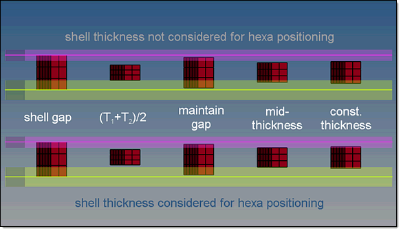
| • | shell gap: With this option the hexa adhesive will project and be touching the shell elements. The position is independent from any thickness. |
| • | (T1+T2)/2: With this option the hexa adhesive size (thickness) depends on the shell thickness of the connected parts. |
| • | mid thickness: With this option the hexa adhesive size (thickness) is calculated as the air gap between the two connected parts. If there is no gap--or even a penetration--the hexa seam size is always modeled with 1.0. |
| • | const. thickness=: With this option the hexa adhesive size (thickness) is directly specified by giving the value. |
| • | maintain gaps=: With this option the hexa adhesive size (thickness) is calculated as the gap distance, minus twice the value specified for maintain gaps. The position is independent from any thickness. |
|
direction node
|
Define the direction node.
|
|
The Penta (Mig) realization type is the primary form of penta realization for areas. For details, see Penta (Mig) in Special Realization Types under the HyperMesh User's Guide chapter on Connectors.
|
|
Input
|
Action
|
connectors
|
Use this selector to specify the connectors that you wish to edit.
Once you alter the selected connectors' options, clicking the edit button updates the selected connectors with respect to the new settings. The connectors will become unrealized.
|
trim
|
Use trim to reduce the size of an area connector in order to make it fit better in the model.
| 1. | Using the connector selector, select the area connector that you would like to trim. |
| 2. | Using the nodelist selector, select a nodelist on the area connector or a nodelist on existing nodes. |
| • | nodelist on an area connector |
|
Trims the first and the last node to the connector area edge within the given snapping distance.
|
| • | nodelist on existing nodes |
|
The line defined by the nodelist is projected normal to the area connector surface, and the connector will be trimmed along that projected line. The line must be long enough to guarantee a full trim.
|
| 3. | To trim the connector at the closest connector point per each selected node within the specified tolerance, select the snap to connector point check box, and enter a tolerance. By default this option is selected, and the tolerance is set to 1.0. If you selected a nodelist on existing nodes, this option will have no influence on the trimming behavior. |
| 4. | To delete the smallest connector piece when the connector is trimmed, select the delete smaller connector piece check box. |
| 5. | Click trim. The connector is immediately trimmed into new, unrealized connectors. The new connectors contain all of the information that was retained from the original connector. |
6. Optional: This action can be rejected.
|
remesh
|
mapped type
|
This switch allows you to determine the shape of element to use on surfaces that can be mapped to simple geometric shapes like a triangle, rectangle, or rhombus.
Following element types are available: quad, tria, mixed, R-tria.
|
free type
|
This switch allows you to determine the shape of element to use on more complex surfaces that cannot easily map to simple shapes.
Following element types are available: quad, tria, mixed, R-tria.
|
size control
|
Use size control to keep the elements roughly the same size.
|
skew control
|
Use skew control to prevent the mesh from producing highly-skewed elements
|
link opposite edges
|
Use link opposite edges to force opposite edges of the area connector to use consistent edge densities, provided that the starting densities are close enough. This creates tapered lines of elements, instead of using trias to transition between inconsistent densities:

Meshing with (left) and without (right) linked edges.
|
size and bias/edge deviation
|
Use this toggle to determine the meshing criteria:
| • | element size: When using the size and bias option, this determines the size of each element. |
| • | min elem size: With the edge deviation option, elements of varying size will never be smaller than this value. |
| • | max elem size: With the edge deviation option, elements of varying size will never exceed this value. |
| • | max deviation: With the edge deviation option, this defines the maximum allowable distance between an edge of the surface being meshed and an element edge. |
| • | max angle: With the edge deviation option, this defines the maximum allowable angle between two element edges. |
|
|
Button
|
Action
|
mesh
|
When remeshing connectors, you must click this command button to apply the mesh using the new settings.
|
options
|
Clicking this command button opens the connector options panel, where various settings can be defined.
|
create
|
Creates the connector(s) with provided input (if sufficient).
|
reject
|
Undoes the last action.
|
return
|
Exits the Area panel.
|
|
See Also:
FE Configuration File
Connector Definition
Connector Realization
Connectors Module
Alphabetical List of Panels


