This panel, accessed from within the Connectors Module or by clicking the options button on the Spot, Bolt, Seam, or Area panels, provides inputs to set general connector options as well as options specific to spots, bolts, seams, or area connectors. In particular, settings which don’t need to be altered very often reside here.
Panel Usage
The panel is organized into subpanels for general options, spot options, bolt options, seam options, area options, apply mass options, and fe config. Each subpanel contains settings appropriate to its connector type. All input on this panel is persistent; your settings remain (are not cleared) when you switch subpanels, or even exit the entire Connector Options panel.
| Note: | When this panel is accessed from one of the other connector panels, leaving the panel returns you to the Connector panel from which it was accessed. If accessed directly from within the Connectors Module, it returns you to the main menu for the module. |
|
Subpanels and Inputs
Consider shell thickness and offset for solid positioning
Enables Engineering Solutions to consider the shell thickness and offset when positioning the connector. When this check box is turned off, the connector is realized to the ideal shell position.
This option influences the ACM realization types. By default, this check box is selected. For more information on how hexas are positioned when this option is selected, refer to Hexa Positioning for Hexa Adhesives & ACMs.
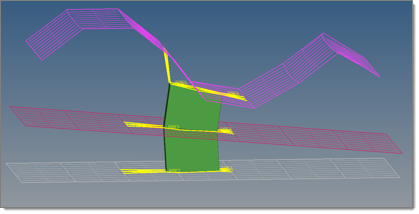
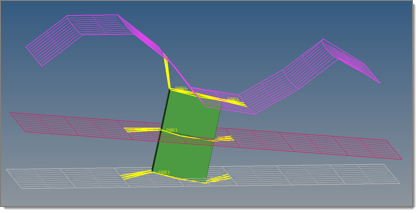
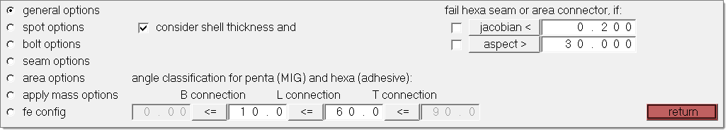
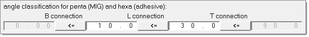
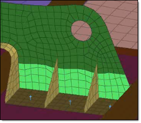
Angle classification for penta (Mig) and hexa (adhesive)
Enables you to specify when a penta (mig) and hexa (adhesive) seam connector becomes a B, L, and T connection.
In the image below, angle classifications have been defined for a hexa (adhesive). A B connection will be created when the hexa (adhesive) has an angle between 0° and 10°, a L connection will be created when the angle is between 10° and 30°, and a T connection will be created when the angle is between 30°and 90°.
Fail hexa seam or area connectors, if:
| • | Jacobian. When selected, hexa seam and/or area connectors will fail if the jacobian value is less than the specified value. |
| • | Aspect. When selected, hexa seam and/or area connectors will fail if the aspect value is greater than the specified value. |
|
Spot options contains inputs for spot connector projection, link conservation, system definition, and end offset or half-spacing of weld locations.
Input
|
Description
|
end offset = / half spacing
|
First and last weld locations are offset from the ends of the line by the end offset value, or by a value equal to half the distance between weld locations.
|
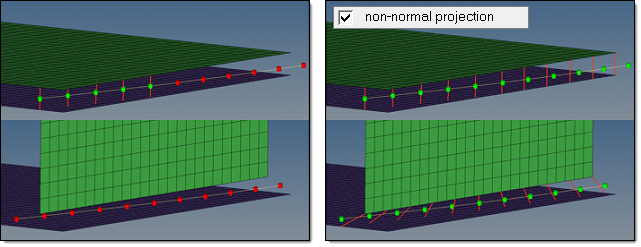
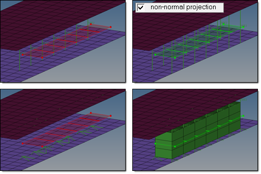
non-normal projection
|
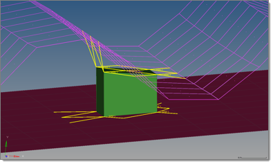
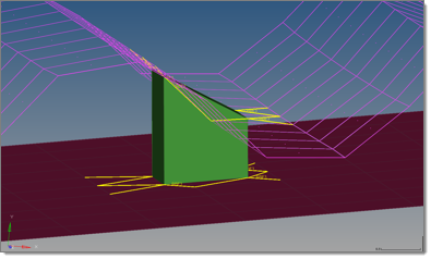
By default this option is deactivated for spots. Typically the link detection requires a valid normal projection to the link candidates (note that an angle of <5° will be considered as normal). If the normal projection is not possible, the realization fails as shown in the example below.
Activating the non-normal projection option waives the requirement for a normal projection, so link candidates only need to be found within the connector tolerance.
In certain cases activating this option may be useful.
|
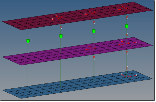
system definition
|
These options allow the creation of coordinate systems along with the creation of simple 1D FE representations. The y-axis is collinear with the 1D element the system is located at.
|
No coordinate system will be created.
|
|
Only one coordinate system will be created, even if it is a multiple layer connection (several 1D elements in a row). The system will be created at one end of the 1D element row.
|
|
Along with every created 1D element, one coordinate system is created at one end.
|
|
Along with every created 1D element, two coordinate systems are created--one at each end.
|
|
links conservation
|
Links conservation defines whether or not extra links should be stored on a spot or seam connector.
|
This is the default setting. During the link detection the link candidates are reduced to the links which are needed to perform a valid projection with respect to the specified number of layers. For example, in a 3-layer spot connector typically three links are established, even though more than three link entities were selected before and are within the given tolerance. For seam connectors this investigation has to be done per each test point, so that typically the number of links is higher than the number of layers.
|
| • | re-apply during realizations |
|
This option only appears if minimum needed links is selected for links conservation.
If this checkbox is checked, unnecessary defined links are removed during realization. Therefore only the links which already exist in the connector are taken into account.
|
|
This option allows storing more link candidates than necessary on a connector. In addition to the number of layers, extra links can be stored per test point. This means with 5 extra links, a 3-layer spot connector can store up to 8 link candidates or a seam (2-layer) with 6 test points can store up to 42 link candidates.
|
|
use normal direction of the closest element to determine links
|
When there are a lot of small components, the wrong components can be determined links. Select this option to add links to spot connectors based on the normal direction of the closest element.
|
orthogonal faces 1 hexa acm
|
Creates ACM hexa elements as orthogonal as possible. This option overrules the normal shell gap option.
If project hexa faces to shell is also enabled, the shell gap will be forced and, at a minimum, the hexa edges for each hexa pointing from one link to the next will be parallel to each other.
|
project hexa faces to shell
|
In some border cases, during ACM (shell gap) spot realization not all nodes of the appropriate hexa(cluster)-side are positioned exactly on the shell. This is due to some simplifications during the projection routine because it is estimated that the shells will not be too curvy and will be pretty plain. Therefore not every node is individually investigated and projected to the same plane as the first one.
Select this option to investigate and project each individual node, enabling you to expect and accept penetrations.
|
|
Bolt options Contains inputs for link conservation when creating or realizing bolts.
Input
|
Description
|
minimum needed links
|
This is the default setting. During the link detection the link candidates are reduced to the links which are needed to perform a valid projection with respect to the specified number of layers. This means that, for example, for a 3-layer spot connector typically three links are established, even though more than three link entities were selected before and are within the given tolerance. For seam connectors this investigation has to be done per each test point, so that typically the number of links is higher than the number of layers.
|
re-apply during realizations
|
This option only appears if minimum needed links is selected for links conservation.
If this checkbox is checked, unnecessary defined links are removed during realization. Therefore only the links which already exist in the connector are taken into account.
|
extra links =
|
This option allows storing more link candidates than necessary on a connector. In addition to the number of layers, extra links can be stored per test point. This means with 5 extra links, a 3-layer spot connector can store up to 8 link candidates or a seam (2-layer) with 6 test points can store up to 42 link candidates.
|
|
Input
|
Description
|
discontinuity weld length tol
|
Defines an upper and lower allowed deviation from the requested discontinuity weld length in %.
| • | allow weld longer by (%) specifies the upper deviation from the requested weld length |
| • | allow weld shorter by (%) specifies the lower deviation from the requested weld length |
|
links conservation
|
Defines whether or not to store extra links on a spot or seam connector.
| • | minimum needed links reduces the link candidates during link detection to the links which are needed to perform a valid projection with respect to the specified number of layers. For example, in a 3-layer spot connector typically three links are established, even though more than three link entities were selected before and are within the given tolerance. For seam connectors this investigation has to be done per each test point, so that typically the number of links is higher than the number of layers. This is the default setting. |
| - | re-apply during realizations removes unnecessary defined links during realization. Only the links which already exist on the connector are taken into account. This option is only enabled when minimum needed links is selected. |
| • | extra links specifies an amount of extra link candidates to store on a connector. In addition to the number of layers, extra links can be stored per test point. This means with 5 extra links, a 3-layer spot connector can store up to 8 link candidates or a seam (2-layer) with 6 test points can store up to 42 link candidates. |
|
link option
|
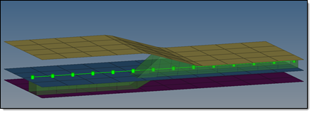
Seam connectors are supposed to connect two links at each test point. Use the link option to specify how connectors are linked.
| • | closest (default). The two closest link candidates are connected during the realization. |
This approach requires the connector be positioned precisely in the middle of the links, especially when there are other close link candidates around.
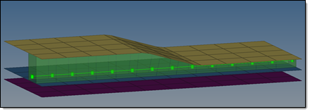
| • | opposite. The connector searches for opposite links on both sides of the connector during realization. |
This option is useful when you are confident that the connector will be correctly positioned between the links. The opposite links must be fairly parallel to each other. To control this, specify a normal projection angle deviation. Ideally the two projection vectors are collinear.
|
|
Input
|
Description
|
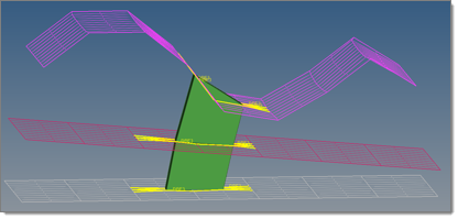
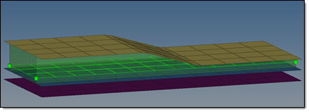
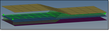
non-normal projection
|
By default this option is deactivated for areas. Typically the link detection requires a valid normal projection to the link candidates.
| Note: | An angle of 5 degrees or less will be considered as normal. If the normal projection is not possible, the realization fails as shown in the example below. |
Activating the non-normal projection abrogates the requirement for a normal projection, so the link candidates only need to be found within the connector tolerance.
In certain cases activating this option may be useful.
|
Link option
|
Area connectors are supposed to connect two links at each test point. Use the link option to specify how connectors are linked.
| • | closest (default). The two closest link candidates are connected during the realization. |
This approach requires the connector be positioned precisely in the middle of the links, especially when there are other close link candidates around.
| • | opposite. The connector searches for opposite links on both sides of the connector during realization. |
This option is useful when you are confident that the connector will be correctly positioned between the links. The opposite links must be fairly parallel to each other. To control this, specify a normal projection angle deviation. Ideally the two projection vectors are collinear.
|
|
Input
|
Description
|
Check for missing link
|
This determines how strict the rerealization criteria are when applying masses.
| • | When this option is selected, before rerealizing an unrealized connector Engineering Solutions will check the links in the connector. If any of the links do not exist, the connector will fail. |
| • | With this option deselected, Engineering Solutions will rerealize any unrealized connector if at least 1 of the links still exists in the connector. |
|
|
In the fe config panel, you can load a custom feconfig.cfg file, and you can unload a feconfig.cfg file that was previously loaded.
If you load a feconfig.cfg file that contains config types with IDs or names that already exist in the current HyperMesh database config list, the duplicated config types will be skipped during the loading process. To overwrite the existing config types with the new config types, select the overwrite if a config ID or name exists check box.
|