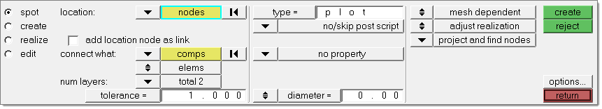
Use the connector Spot panel to create connectors that represent point connectors such as spot welds. These connectors can be realized as standard or custom weld representations.
When the Spot panel is active, only spot-type connectors display in the graphics area; graphics for other connector types are suppressed until you exit the panel.
Panel Usage
The panel is organized into subpanels, but each of the first three subpanels are organized similarly (see Subpanels below for details.)
Information on each panel is independent, so anything specified on one subpanel will not carry over to another. Such information is also non-volatile while you remain inside the Spot panel, so you will not lose work by changing from one subpanel to another. You will, however, lose settings by leaving the Spot panel and then returning.
Subpanels and Inputs
The Spot panel contains the following subpanels and command buttons:
| • | Spot: The spot connector is both created and realized simultaneously. |
| • | Create: The spot connector is created only--no realization occurs on this subpanel. |
| • | Realize: An existing spot connector is realized only--no creation options exist on this subpanel. |
| • | Edit: an existing spot connector gets edited. |
The spot, create and realize subpanels use the same set of entry controls. They are organized in three different columns:
| 1. | The first column contains everything related to connector creation and link detection. |
| 2. | The second column contains everything related to realization type, post script and property assignment. |
| 3. | The third column contains everything related to the final connection to the link entities. |
These columns and their organization are illustrated in detail in Connector Panel Structure in the Connectors chapter. See Special Realization Types in the Connectors chapter for further information on specific realization types.
From the Spot panel you also have direct access to the Connector Options panel, where general and connector type-specific settings can be set. In particular, settings which don’t need to be altered very often are provided there.
Input
|
Description
|
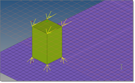
location
|
Specify the location of the connector to be created by selecting one of the following:
nodes
Select an existing node (also temp nodes).
points
Select an existing point (fixed point or free point).
nodelist
Select a node list and specify spacing or density and end offset.
The selected nodes are used to internally create a smoothed line, which is used exactly as a real line. The connector will not remember the position of the selected nodes, unless you select the preserve nodes check box.
lines
Select a line and specify spacing or density and end offset.
|
add location node as link
|
Stores the selected location node as an additional link of the Link Type node.
This check box appears when the location is defined by nodes. Many realization types do not work together with nodes as links. When these realization types are chosen the option is not provided.
| Note: | Connectors can be created with different types of entities; for example, a connector can be defined by selecting a component on one side and a tag on the other side. This can be done by creating a spot connector to specify one of the entity types and selecting that entity. Add the second entity by updating the connector via the add links functionality in the Connector browser or the Add Links panel. |
|
spacing / density
|
Distance between each weld location on the line (spacing) or number of weld locations on the line (density). The number of weld points is approximated to the closest integer, based on the length of the line and spacing given while considering the end offset (or half spacing) value given on the Connector Options panel. The spacing is also calculated based on the length of the line and density for the half-spacing option.
|
preserve nodes
|
Preserves the position of the nodes when you create and realize a connector.
This check box is only available if the location is defined by a nodelist/nodepath.
|
split to points
|
Splits the line into individual points and creates spot connectors for each resultant point.
This check box is only available if the location is defined by a nodelist/nodepath or by a line.
|
connectors
|
Specify the spot connectors to be realized.
This only appears on the realize and edit subpanels.
|
connect what
|
Select the link entities which should become link candidates. Link candidates are certain entities of a chosen Link Type, which are supposed to be connected during the realization. Entities outside the tolerance are not taken into account.
comps
Select the components to be added as link entities. You can choose to connect to either the geometry or elements of the selected components.
assems
Select the assemblies to be added as link entities. You can choose to connect to either the geometry or elements of the selected assemblies.
surfs
Select the surfaces to be added as link entities. You can choose to connect to either the geometric surfaces or elements associated to the selected surfaces.
elems
Select the elements to be added as link entities.
nodes
Select the nodes to be added as link entities.
tags
Select the tags to be added as link entities.
|
geom/elems
|
Link State:
Connect to either the geometry or the elements of selected link entities. Only available when connect what is set to comps, assems, or surfs.
|
num layers
|
Select the number of layers that have to be connected at the connector position.
When the link detection is performed the valid connector links are established with respect to the given tolerance and the selected link candidates. By default the links are reduced to the minimum needed ones. Typically for spots the number of layers is identical to the number of links, though the number of links can be lower in case of flaps.
For spot connectors it is possible to set the number of layers to auto in order to identify and write the exact number of layers during link detection to each individual connector.
See also: Link Conservation in the Connector Options panel.
|
tolerance
|
The tolerance defines a distance from the connector location. Only entities within this tolerance can be taken into account for the link detection and the final realization. Thus, the tolerance is used twice: first for the link determination and then again for the realization. In the second step the tolerance is used to verify whether adequate link candidates are available to be connected with respect to the number of layers.
During pure connector creation on the create subpanel the tolerance is used for the link determination, but not necessarily stored on the connector (unless the checkbox in front of the tolerance field is marked). In this way, different tolerances can be used.
| Note: | The tolerance used during the realization process is always written to the connector. |
|
connect when
|
This connector rule defines when to perform the link detection. Select one of the following options:
now
Adds link entity information now, directly together with the connector creation.
at fe-realize
Creates a connector without any specific information regarding its links. The links are determined when performing the final realization with respect to the connector position.
Using this option defines the re-connect rule at fe-realize for all created links.
|
re-connect rule
|
While realizing the connector, Engineering Solutions looks for link entities based on the re-connect rule:
none
No re-connect rule is defined. If the link entity is not currently in the model, the connector with this re-connect rule will fail to realize.
If no re-connect rule is defined for a link, this link disappears from the connector when the linked entity is deleted.
Use id
Uses the selected link entities' IDs to re-connect. If the link entity is not currently in the model, the connector with this re-connect rule will search for entities with the same ID.
Use name
Uses the selected link entities' names to re-connect. If the link entity is not currently in the model, connectors using this re-connect rule search for entities with the same name.
This option is useful in situations where the parts to be connected have been changed/replaced.
|
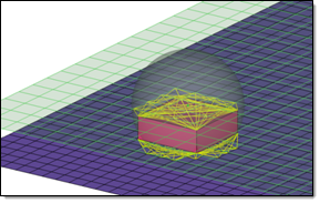
use rbe3 radius
|
This option is only available for the realization type acm (general).
RBE3 elements are typically created with three or four legs dependent on the element type (quadface, triaface) the projection of the appropriate hexa node is landing on. To be more accurate, especially regarding different mesh sizes, an rbe3 radius can be defined, so that more nodes nodes can be joined by each RBE3 element. In any case, at least one element face will be joined by each RBE3 element.
When the use rbe3 radius check box is cleared:
When the use rbe3 radius check box is selected:
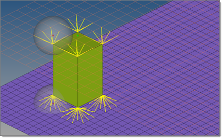
All of the nodes of the appropriate link (outer nodes, if it is a solid link), which are positioned inside a sphere around the projection point, are considered to be joined to the RBE3 element. A feature angle is also considered. The nodes that are on a different side of the feature edge than the projection point will not be joined to the RBE3 element.
When this option is activated, specify the following:
| • | rbe3 radius - defines the search radius |
| • | feature center - defines which projection point(s) are used as the radius center. |
Individual rbe3
|
Cluster center
|
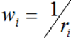
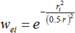
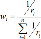
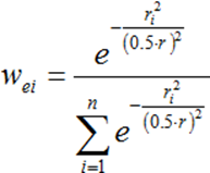
| • | weight factor - defines which formula should be used for the calculation. |
|
|
Inverse distribution
|
Normal distribution
|
| • | normalize rbe3 weights - allows for the normalization of all the weights per a single rbe3. |
|
|
Normalized inverse distribution
|
Normalized normal distribution
|
| • | feature angle - defines the feature angle to be considered. |
|
|
Input
|
Description
|
type
|
Specifies the realization type to use for realization. The realization types available depends on the configuration file loaded under fe file on the general options subpanel of the Connector Options panel.
The realization type is a description of the FE representation. The provided list depends on the active user profile.
|
post script treatment
|
Specifies whether or not a post script has to be used for the specific realization type. These scripts are used to automatically create materials, properties, and/or contacts necessary for realizing the connectors.
|
Default for any realization type having a post script defined in its FE configuration.
|
|
Specify your own TCL file which should be used. Such a file can perform a special treatment on the FE representation.
|
|
Default for all realization types without any post script defined. No post script is used.
|
|
elems to current comp / elems to connector comp
|
Specifies which component the FE representations are stored in once they have been realized.
|
stores newly created FE representations in the current component (displayed in the status bar).
|
|
stores newly created FE representations in the same component that the connector was originally created in.
|
This toggle only displays on the realize subpanel if no/skip post script is used.
|
property / no property
|
Specifies whether or not a certain property gets assigned.
|
Select a pre-defined property to assign to all newly created elements.
|
|
No property gets assigned to all newly created elements.
|
This option only displays if no/skip post script is used.
|
direct property assignment
|
Assigns a property directly. If this check box is cleared, the property is assigned to the destination components.
This option only appears when the property treatment property = is chosen and the user profile is Nastran, OptiStruct, RADIOSS or Abaqus.
|
|
Input
|
Description
|
diameter / use diameter mapping
|
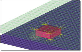
This field is used for realizations based on hexa elements such as ACM, where the size of the realized element (hexa, and so on) is created based on the diameter value, or for certain realization types where the diameter is used by a post script.
The size of the hexa face is calculated from the diameter value  . .
When you have weld nuggets from hexa patterns (more than one hexa), the diameter will be measured from two opposite nodes.

Hexa
|

Weld Nugget
|
Diameter enables you to specify a single diameter value, whereas Use diameter mapping obtains diameter values that you assigned to a range of flange thicknesses in the Diameter Table. Along with flange thickness ranges, you can also specify the main flange thicknesses to consider when assigning diameter values. See Diameter Table for more information.
|
Input
|
Description
|
thickness
|
The thickness options below are used for dimensioning and positioning the hexas:
shell gap
The hexa spot will project and be touching the shell elements. The position is independant from any thickness.
equival. (T1+T2)/2
Creates hexa elements with RBE3 elements projecting and connecting to the surrounding shell elements. This realization uses the shell thickness to calculate the hexa offset from the shell elements. In the case where the model is a 3T connection, the acm (equivalenced-(T1+T2)/2) realization will join the hexa elements.
detached (T1+T2)/2
Creates hexa elements with RBE3 elements projecting and connecting to the surrounding shell elements. This realization uses the shell thickness to calculate the hexa offset from the shell elements. In the case where the model is a 3T connection, the acm (detached-(T1+T2)/2) realization will not join the hexa elements.
mid thickness
The hexa spot size (thickness) is calculated as the air gap between the two connected parts. If there is no gap, or even a penetration, the hexa spot size will always be modeled with 1.0.
const thickness
The hexa spot size (thickness) is directly specified by entering a value.
maintain gaps
The hexa spot size (thickness) is calculated as the gap distance reduced by two times the specified value for maintain gaps. The position is independant from any thickness.
|
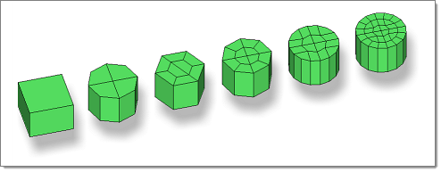
num hexas
|
This option appears for all ACM realization types, and allows you to create a hexa cluster with 1, 4, 8, 12, 16 or 32 hexas, which are arranged in a predefined pattern:
|
coats
|
Defines the number of hexa elements required along the thickness. Multiple solid coats are supported.
|
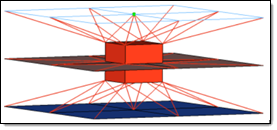
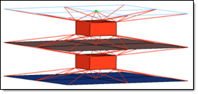
orthogonal faces
|
Forces the creation of perfectly orthogonally-shaped hexas.
This check box appears for any kind of ACM weld, if num hexas is set to 1.
In the picture below (an extreme situation) the two leftmost realizations were performed with the orthogonal faces option active.
|
|
Input
|
Description
|
create vector
|
Creates orthogonal vectors for each CBUSH element created during the sealing realization. These vectors are used to define the orientations of the CBUSH elements, which is important to the stiffness defined in the related PBUSH cards.
|
|
Input
|
Description
|
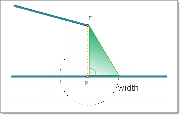
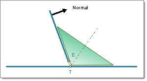
width
|
Specifies the length of a penta.
Available for: penta (mig + L), penta (mig + T), and penta (B).
|
depth
|
Specifies the depth of a penta.
Available for: penta (mig + L), penta (mig + T), and penta (B).
|
fitted/equilateral/ equilateral-fitted
|
Defines the size and shape of the penta.
Available for: penta (mig + L).
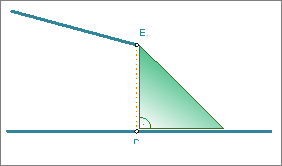
fitter
The length of one penta edge is the exact projection distance, and the length of the other penta edge is defined by the width value; the penta has an right-angle.
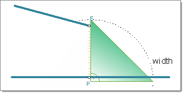
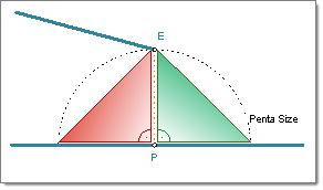
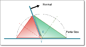
equilateral
Creates an equilateral penta; leg lengths are defined by the width value.
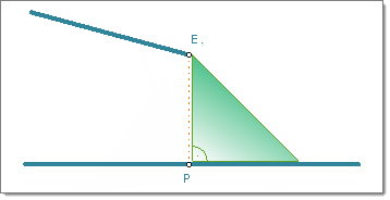
equilateral/fitted
Combination of fitted and equilateral; you do not need to define a width when you select this option.
|
right-angled
|
Select this check box to create a right-angled penta that is oriented around the bisector. If this check box is cleared, an angle adapted penta will be created.
Available for: penta (mig + T).
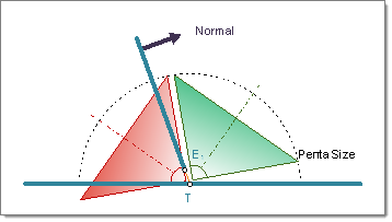
Right-angled T-weld penta created on both sides of the normal.
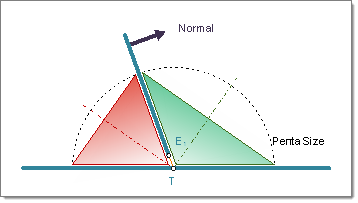
Angle adapted T-weld penta created on both sides of the normal.
|
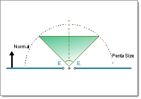
both sides/positive sides/negative sides
|
Specifies which side of the normal to create the penta on.
Available for: penta (mig + L), penta (mig + T), and penta (B).
(mig + L)
The negative side is the side where the links are fairly parallel to each other. The angle that is close to 90° (88° to 90°) the element normal of the first found shell element at the free edge decides which side is the positive and the negative side.
Penta (mig+L) one side
|
Penta (mig+L) two side
|
(mig + T)
The positive side is normally the side with the obtuse angle. The angle that is close to 90° (88° to 92°) the element normal of the first found shell element at the free edge decides which side is the positive and negative side.
Penta (mig+T) one side, positive side
|
Penta (mig+T) two side, positive and negative side
|
(mig + B)
The positive side is the side where the element normal of the first link points to.
Penta (mig+B) one side
|
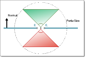
Penta (mig+B) two side
|
|
|
Input
|
Description
|
use shortest projection for center
use connector position for center
use coarse mesh for center
|
use shortest projection for center
The closest node becomes the center of the RBE3 element.
During the realization based on the connector position and the tolerance the closest links are determined up to the number of required layers (num layer). All other link candidates are not taken into account for the next step. The closest node is also determined, and it becomes the center of the RBE3 element. Based on this center position all nodes within the given tolerance (distance from center to node) and belonging to the remaining links are attached to the RBE3 element.
If the connector has been created with the option add location node as link, the option use shortest projection for center is ignored and the linked node becomes the center of the RBE3 element.
use connector position for center
The exact position of the connector becomes the center of the RBE3 element.
use coarse mesh for center
During the realization based on the connector position and the tolerance, the closest links are determined up to the number of required layers (num layer). All other link candidates are not taken into account for the next step. From the remaining links the one with the coarsest mesh is identified and a node on this mesh (close to the perpendicular connector projection) becomes the center of the RBE3 element. Based on this center position all nodes within the given tolerance (distance from center to node) and belonging to the remained links are attached to the RBE3 element.
If the connector has been created with the option add location node as link, the option use shortest projection for center is ignored and the linked node becomes the center of the RBE3 element.
|
max nodes per layer
|
Specify the maximum number of nodes per layer to attach to the RBE3 element. The minimum number of nodes you can specify is 3.
|
|
Input
|
Description
|
use shortest projection for center
use connector position for center
(Only available for type CWELD (general), when the nodetype GS (point to face) is selected)
|
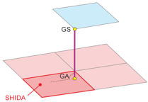
use shortest projection for center
From the connector position the closest node (shell or solid) is identified. This node becomes the GS node.
If a node is defined as link, this option will be ignored and use connector position for center is selected instead.
use connector position for center
The connector position is used for the later GS node.
If the connector has a node link defined, this node becomes the GS node. This can be used to create a CWELD attached to a SPC node.
If the connector is very close to an existing node of a link (shell, solid, 1D element), this node will be taken as a GS node.
If the connector is somewhere in space, a tempnode is created at that position and then taken as a GS node.
|
CWELD Type
|
CWELD type definition.
Only available for type CWELD (general).
|
Nodetype
|
The nodetypes available depend upon the CWELD type selected.
ELEMID
|
GA-GB
|
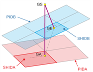
GS (face to face)
|
GS (point to face)
|
GRIDID
|
GA-GB
|
GS (face to face)
|
GS (point to face)
|
PARTPAT
|
GA-GB
|
GS (face to face)
|
ELPAT
|
GA-GB
|
GS (face to face)
|
ALIGN
|
GA-GB
|
GS(face to face)
|
GS (point to face)
|
Only available for type CWELD (general).
|
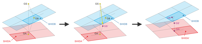
recenter GS
|
When enabled, the initial GS position is re-positioned between node GA and GB. After re-positioning, projections are done a second time to identify the correct node/element IDs.
Only available for type CWELD (general), when the nodetype GS (point to face) is selected.
|
centered quad
|
When enabled, a mesh modification is performed during the realization to guarantee that the CWELD nodes will be close to the CQUAD centroids.
Specify a desired quad size in the quad size field, or click centered quad to access additional centered quad tolerance settings.
Only available for type CWELD (GA-GB ELEMID) and CWELD (GA-GB GRIDID).
|
|
|
The effects of these options are illustrated in detail in the Spot Panel Realization Methods topic of the HyperMesh User's Guide.
Input
|
Description
|
mesh dependent/
mesh Independent
|
Determines whether the realizations require a node connection. For a realization which doesn’t need any node connection and the connection is primarily defined via a solver-specific card or the nodes which need to be connected are just defined by a cylinder, then use the mesh independent option. In all other cases the mesh dependent option should be used.
|
adjust realization / adjust mesh
|
Determines whether the mesh should be locally adjusted (such as creating transition elements, or remeshing) to ensure proper realization, or if the realization itself should be adjusted--such as allowing non-normal realizations for the sake of locating nodes to create the realization.
This option only displays when mesh Independent is active.
|
quad transition / remesh / smooth
|
The following mesh adjustment options are available to select from this toggle:
quad transition
Creates quads to serve as a transition.
remesh
Remeshes the linked entities to achieve better links.
smooth
Adjusts the mesh in such a way that the closest node to each layer is moved into the position of the projection point. The advantage of this option is that neither the element IDs nor the node IDs will be changed, and the element topology will remain the same.
This toggle only displays when the mesh dependent and adjust mesh options are active.
|
imprint / skip imprint
|
Imprinting is a method of merging two meshes from two different link entities to create a transition mesh that matches up well with both. See mesh edit - imprint for connectors for more details. If you choose skip imprint, close-set connectors' transition quads may overlap and interfere with each other, causing one or more realizations to fail.
This toggle only displays when the mesh Independent, adjust mesh, and quad transition options are active.
|
resolve conflicting imprints
|
Small conflicts between overlapping transition meshes can be resolved automatically. Larger conflicts may require a manual imprint, as described in mesh edit - imprint for connectors.
This toggle only displays when the mesh Independent, adjust mesh, quad transition, and imprint options are active.
|
allow snapping
|
This check box only displays when the mesh Independent, adjust mesh, and quad transition options are active.
|
quad size
|
Specify a preferred size for the transition quads; use the check box to activate or deactivate the use of this size. When inactive, the meshing engine will use the default element size from the Options panel.
This check box and text box only displays when the mesh Independent, adjust mesh, and quad transition options are active.
|
find nearest nodes / project and find nodes / ensure projection
|
Determines how the realization will adjust to locate nodes in the linked entities in order to establish links. This decision can be quite involved; see the explanations of each option in detail in the Spot Panel Realization Methods topic of the Engineering Solutions User's Guide.
This switch is only available when adjust realization is active.
|
|
See Also:
FE Configuration File
Connector Definition
Connector Realization
Connectors Module
Alphabetical List of Panels


