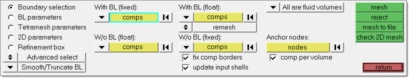
Use the BL parameters subpanel to specify the general boundary layer behavior. These settings affect how other CFD subpanels generate mesh when meshing with boundary layers.
Panel inputs
Input
|
Action
|
BL thickness: Number of Layers
|
Specifies the total number of layers to be generated using the specified first layer thickness and growth rate.
This option is only available when Smooth BL is selected.
|
BL thickness: Total Thickness
|
Specify the BL thickness, but not the number of layers.
This option is only available when Smooth BL is selected.
|
BL thickness: Ratio of Total Thickness/Elem Size
|
Ratio between the total boundary layer thickness and the average element size of the base surface elements.
This option is only available when Smooth BL is selected.
|
Exponential Boundary Layer / Structured Isotropic Layers
|
Choose between Exponential Boundary Layer and Structured Isotropic Layers.
This option only appears if Native BL is selected.
|
Simple settings
|
Will grow BL until it matches final layer height/base surface size ratio. The number of layers to grow are decided based on the inputs.
This option only appears if Smooth/Truncate BL is selected.
|
User controlled
|
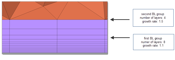
Define settings for two BL groups. The purpose of the first BL group is to define BL with a smaller growth rate to better physics capturing. Second group enables a smooth transition between BL layers and the tet core. User controlled enables BL to grow with a higher growth rate until the final layer height is X * the base size/tetra layer size. (X is the Final layer h/base ratio that you define.)
This option only appears if Smooth/Truncate BL is selected.
|
First layer thickness
|
Indicate the thickness of the first layer. If you are unsure what thickness to use, access the First cell height calculator to calculate it.
|
BL growth rate
|
Non-dimensional factor that controls the change in layer thickness from one layer to the next.
|
Acceleration
|
A growth acceleration for boundary layers beyond the first few layers; in effect, this acts as a growth rate on the growth rate, but only after the first few initial boundary layers.
By default, the first two boundary layers grow by the growth rate as described above. However, subsequent layers grow by the growth rate multiplied by the acceleration factor. Thus, if d is the initial thickness, r is the initial growth rate, and a is the acceleration rate, then the thicknesses of the successive layers are d, d*r, d*r*(r*a), d*r*(r*a)^2, and so on.
This option only appears if Native BL is selected and Exponential Boundary Layer is chosen.
|
BL hexa transition mode: Simple Pyramid
|
Uses one pyramid element to transition from a BL hexahedral’s quad face to the tetrahedral core mesh. The height of these pyramids is controlled by simple transition ratio parameter, which represents the ratio between the transition pyramid height and the characteristic size of the base quad.
This option is only available when Smooth BL is selected.
|
BL hexa transition mode: Smooth Pyramid
|
Generates a transition layer composed of pyramid and tetrahedral elements. The thickness of this layer is controlled by the parameter smooth transition ratio, which represents the ratio between the transition layer thickness and the characteristic size of the base quads.
This option is only available when Smooth BL is selected.
|
BL hexa transition mode: All Prism
|
If there are any quad elements in the surface mesh, those will be split into two trias each so that there is no need to transition from quad faces to tria faces when transitioning from the last boundary layer to the tetrahedral core. This option is very important when there are quad elements on areas with (low) distributed BL thickness ratio, because in such areas the thickness of the transition elements (for example simple pyramid) was not taken into account when doing the interference study to assign distributed BL thickness ratio to those elements.
This option is only available when Smooth BL is selected.
|
BL hexa transition mode: All Tetra
|
Generates tetra elements only in the boundary layer and will split the quad elements of the surface mesh into tria elements.
This option is only available when Smooth BL is selected.
|
Export settings
|
Saves the settings to a file.
|
Create prism elements
|
If left unchecked, the mesher will create tetra elements rather than triangular prisms.
Displays only when Native BL is selected.
|
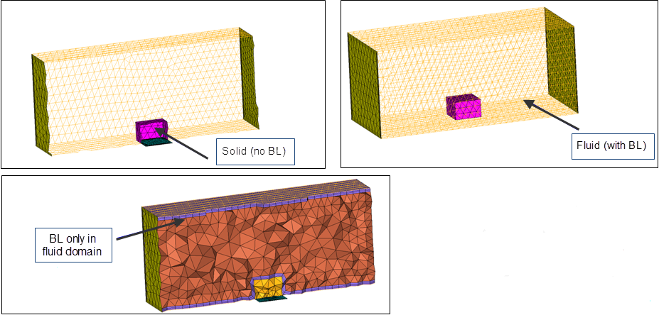
BL only
|
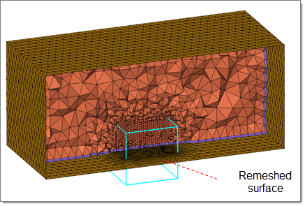
This option generates only the boundary layer, stopping before generating the tetrahedral core. It also modifies adjacent surface meshes to reflect changes introduced by the boundary layer thickness, and creates a collector named ^CFD_trias_for_tetramesh that is typically used to generate the inner core tetrahedral mesh using the Tetramesh parameters subpanel.
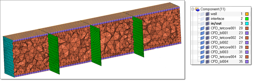
Boundary layer elements are placed in a collector named CFD_boundary_layer and the core tetrahedral elements in another collector named CFD_Tetramesh_core. Both collectors are automatically created if they do not exist. However, that if these collectors do, it might make sense to empty them before meshing; otherwise there will be more than one set of elements occupying the same physical volume. If you mesh the volume in several steps (multi-volume meshing), then you might not want to empty the collector before generating the mesh for the next adjacent volume.
|
BL reduction
|
Displays when Smooth BL is selected.
Define the parameters for scaling the boundary layer thicknesses to avoid narrow or closed channels.
Several BL reduction mechanisms are available, and can be combined with each other.
| • | Dynamic checkbox: This is a one step approach. The proximity check for the BL is performed while the layers are generated and the BL thickness is adjusted accordingly. The advantage of this method is that no estimated BL is used, and therefore a more accurate BL thickness reduction can be performed. |
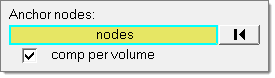
| • | Pre calc checkbox: This is a two step approach. In the first step, the BL scaling factors are defined before the BL is actually grown. These factors describe how much the total BL thickness is reduced at a particular location. For example, a value of 0.5 will reduce the BL thickness to one half of its initial thickness. The scaling factors are stored in a load collector called CFD_BL_Thickness. Using the Auto option, the BL scaling factors are computed automatically based on an estimated boundary layer. Using the Manual option, you can define the scaling factors on components or individual nodes. In the second step, the BL is generated considering the BL scaling factors from step one. |
|
1st cell height calc
|
Calculates the first cell height via the First cell height dialog.
|
Advanced settings
|
This button is available when Smooth BL and Smooth/Truncate BL are selected, however the options in the Advanced BL parameters dialog differ depending on your choice of boundary layer options. See below for more information.
|
Clicking Advanced settings opens the Advanced BL parameters dialog, enabling access to BL gen speed vs quality, Sharp edges handling, BL propagation controls, Proximity controls and Quality controls. Parameters in advanced settings provide more power to you to control BL in special cases, such as sharp corners and close proximity elements.
sharp corner
|
|
close proximity
|
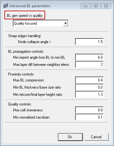
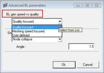
The functionality BL gen speed vs quality contains three options, controlling the growth of the boundary layers.
| • | Quality focused: A set of meshing parameters is used, which ensures a good quality boundary layer in most cases. |
| • | Meshing speed focused: The meshing parameters are chosen in a way that the meshing time is minimized and an acceptable boundary layer quality is achieved in most situations. |
| • | User defined: You can define the relevant parameters individually. When User defined is selected, three additional options are exposed in the dialog: Interpolated layers, Residual threshold and Maximum smoothing iterations. |
For the generation of boundary layers (BL), three parameters are used to control the quality and the required meshing time.
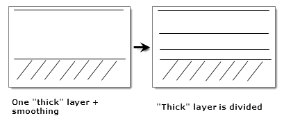
| - | This option defines the number of layers that are generated by interpolation. For example, for a value of three one "thick" layer will be generated and the smoothing step to improve the element quality will be performed. Then, the "thick" layer will be split into three layers, and the spacing is defined by the BL growth rate. In general a large number of interpolated layers will decrease the meshing time but might also decrease the element quality. |
| - | This option defines the stopping criteria (upper bound) for the smoothing step during BL generation. For each new layer smoothing steps are applied to improve the element quality and the overall BL quality. The smoothing step is an iterative process and the smoothing residual is a measurement for the quality of boundary layer, meaning the smaller the residual the better the BL quality. In general, a small residual threshold ensures good quality of the boundary layer but might require more CPU time (under the assumption that the value for maximum smoothing iterations is set large enough). A relatively large residual threshold will usually decrease the CPU time and also decrease the element quality. |
| • | Maximum smoothing iterations: |
- This option defines the maximum number of smoothing steps allowed to improve the element quality in the boundary layer.
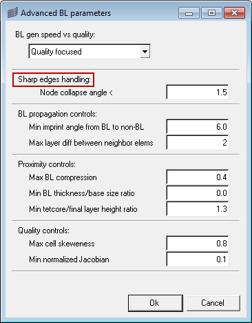
The functionality Sharp edges handling contains the Node collapse angle option for the BL generation at a baffle's free edge and sharp corners pointing into the volume.
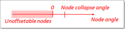
| • | Node collapse: For some surface mesh nodes it is mathematically impossible to compute a normal offset direction for growing the boundary layers. Those nodes are called unoffsetable nodes and require the BL to collapse. |
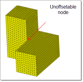
For complex geometry, some surface mesh nodes are often close to being an unoffsetable node, causing problems during BL generation since the computation of the normal offset direction is not straight forward.
Use Node collapse to specify a threshold for boundary layer collapse. For each node a node angle can be computed, which is a function of the normals of the attached elements. If the node angle is below the threshold, the boundary layer will collapse. For an unoffsetable node, the node angle is zero or negative.
This enhancement enables the growth of boundary layers, even on very complex geometry.
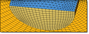
Baffles
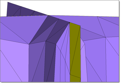
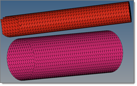
This image shows a baffle (in yellow) with the Node collapse option selected.
The BL is collapsed along the free edge of the baffle.
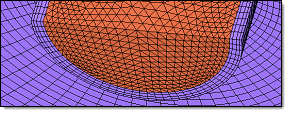
Sharp edge
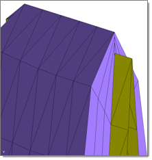
The image above shows a sharp edge (in yellow) with
the Node collapse option selected. Only one normal
is generated at the sharp edge to generate the BL.
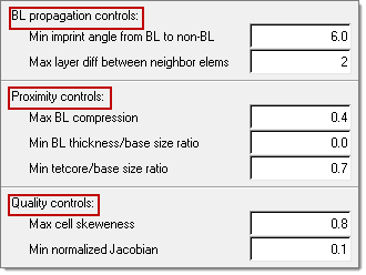
BL propagation controls: Controls how to propogate BL in special cases.
| • | Min imprint angle from BL to non-BL: (recommended range is 6-10). This parameter controls which cases you want to imprint BL on without BL components. If the angle between the BL component and the non BL component is really high imprinting will create high aspect ratio elements. If the angle between BL and No-BL entities (component elements) is less than the imprint angle or greater than (180-imprint angle) it will collapse the BL, rather than imprint on non-BL entities. |
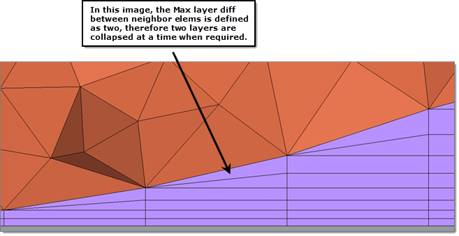
| • | Max layer diff between neighbor elems: (recommended range depends on how many layers you are growing). This parameter controls the maximum layer difference between neighboring elements. This helps to avoid a situation where all BLs collapse at once. This parameter also provides smooth BL transition in case of BL truncation. One fourth of the total BL layers is a good number for this parameter. It also depends on layer height. |
Proximity controls: Special treatment for close proximity area.
| • | Max BL compression: (recommended range is 0-0.6). When there is not enough space available for BL to grow, this parameter enables BL compression, or squeezing. Entering a value of zero enforces no BL compression, which is useful if you want to maintain BL height. Entering a value of one enables the maximum possible compression. First, the BL will try to compress by the max BL compression factor. For example, if the original total BL height is defined as 1, with 0.4 max BL compression, it will try to squeeze the BL layers until 0.6 of the total height. After compressing BL until this value, if there is not enough space the mesher will start chopping off layers. |
| • | Min BL thickness/base size ratio: By default this value is zero, which disables the effects of this parameter. Sometimes due to close proximity the BL will only be able to generate one to two layers (very small total BL height at that location). It might be possible that at that location the transition between BL layers and tet core is very bad. With this factor, if the total BL height is less than the defined factor base size, it will chop off all of the BL layers. |
| • | Min tetcore/base size ratio: The default value is 1.3, which is the recommended value. After creating BL in close proximity, there will be a small space available for tetramesh. This results in high aspect ratio tet elements. This parameter controls the minimum height of tet core as a factor of the final layer height. |
Quality controls: Controls the quality of boundary layers. If the quality of the BL will not meet any of the two criterion, the layer will be trimmed.
| • | Max cell skeweness: (recommended range is 0.8-0.95). With this parameter you can avoid creating highly skewed elements. The tetra mesher sometimes creates better quality elements compared to the BL mesher. It is best to define a higher value if your input 2D mesh has bad element quality and topology. Any BL cells exceeding the max cell skewness will be chopped off. |
| • | Min normalized Jacobian: (recommended range is 0.05-0.2). Any BL cells exceeding the min normalized Jacobian will be chopped off. This parameter avoids generating negative elements. |
|
Clicking Advanced settings opens the Advanced BL parameters dialog, enabling access to BL gen speed vs quality and Sharp edges handling. Parameters in advanced settings provide more power to you to control BL in special cases, such as sharp corners and close proximity elements.
sharp corner
|
|
close proximity
|
The functionality BL gen speed vs quality contains three options, controlling the growth of the boundary layers.
| • | Quality focused: A set of meshing parameters is used, which ensures a good quality boundary layer in most cases. |
| • | Meshing speed focused: The meshing parameters are chosen in a way that the meshing time is minimized and an acceptable boundary layer quality is achieved in most situations. |
| • | User defined: You can define the relevant parameters individually. When User defined is selected, three additional options are exposed in the dialog: Interpolated layers, Residual threshold and Maximum smoothing iterations. |
For the generation of boundary layers (BL), three parameters are used to control the quality and the required meshing time.
| - | This option defines the number of layers that are generated by interpolation. For example, for a value of three one "thick" layer will be generated and the smoothing step to improve the element quality will be performed. Then, the "thick" layer will be split into three layers, and the spacing is defined by the BL growth rate. In general a large number of interpolated layers will decrease the meshing time but might also decrease the element quality. |
| - | This option defines the stopping criteria (upper bound) for the smoothing step during BL generation. For each new layer smoothing steps are applied to improve the element quality and the overall BL quality. The smoothing step is an iterative process and the smoothing residual is a measurement for the quality of boundary layer, meaning the smaller the residual the better the BL quality. In general, a small residual threshold ensures good quality of the boundary layer but might require more CPU time (under the assumption that the value for maximum smoothing iterations is set large enough). A relatively large residual threshold will usually decrease the CPU time and also decrease the element quality. |
| • | Maximum smoothing iterations: |
- This option defines the maximum number of smoothing steps allowed to improve the element quality in the boundary layer.
The functionality Sharp edges handling contains the Node collapse and Multiple normals options.
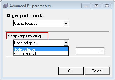
| • | Node collapse: For some surface mesh nodes it is mathematically impossible to compute a normal offset direction for growing the boundary layers. Those nodes are called unoffsetable nodes and require the BL to collapse. |
For complex geometry, some surface mesh nodes are often close to being an unoffsetable node, causing problems during BL generation since the computation of the normal offset direction is not straight forward.
Use Node collapse to specify a threshold for boundary layer collapse. For each node a node angle can be computed, which is a function of the normals of the attached elements. If the node angle is below the threshold, the boundary layer will collapse. For an unoffsetable node, the node angle is zero or negative.
This enhancement enables the growth of boundary layers, even on very complex geometry.
Baffles
This image shows a baffle (in yellow) with the Node collapse option selected.
The BL is collapsed along the free edge of the baffle.
Sharp edge
The image above shows a sharp edge (in yellow) with
the Node collapse option selected. Only one normal
is generated at the sharp edge to generate the BL.
| • | Multiple normals allows you to specify a threshold angle to control the normal computation on a sharp edge pointing into the volume, or on the free edge of a baffle. If two adjacent elements enclose an angle smaller than the threshold (meaning a sharp edge pointing into the volume), two normals are computed on that edge and the boundary layer will consider the two normals. Otherwise, only one normal is considered. For baffles (zero thickness walls), the option will use two normals at the free edge to generate the boundary layer. |
|
|