|
»Click here to display Table of Contents«
|

Loads Summary |

|

|

|

|
|
Loads Summary |
|
|
|

|
|
»Click here to display Table of Contents«
|
Loads Summary |
|
|
|
|
|
Loads Summary |
|
|
|
|
The Loads Summary tool creates a summary of the loads (node-based forces or moments, and element-based pressures) applied to a model. This utility opens in the Tab Area.
The utility summarizes the loads contained within one or more load collectors, and sums these loads about the global origin by default. You can also specify a sum node about which to sum the loads, instead of the origin.
The force from a pressure is calculated by taking the pressure components and multiplying them by the appropriate element’s face area. The corresponding forces are then assumed to be applied at the face centroid.
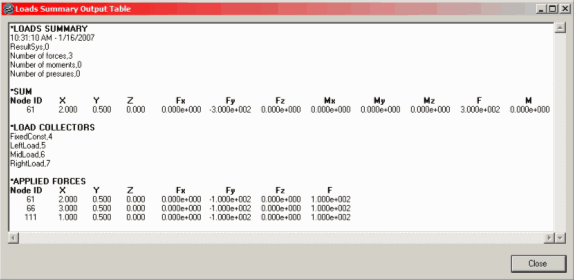
Below is an example of the summary table:
The Loads Summary utility includes the following controls:
Input |
Action |
Select all/none/reverse |
Use these three buttons to select all of the listed load collectors, none of them, or to reverse the selection (deselects any currently selected collectors and selects any collectors not currently selected). |
name filter |
Used to filter the load collectors based on collector name. For example, if all of your forces are in collectors beginning with the prefix "force" and followed by unique numbers, you could hide the collectors that don’t begin with "force" by entering force* into the filter text field. |
Collector list |
All of the load collectors in the HM database display in this list. Click a load to select it, or use <shift>-click or <ctrl>-click to select multiple loads. |
Result System |
This defines the coordinate system in which the summary is output. Values coming from the load collector are transformed into this system. If a system does not exist, you can create it on the fly. If a system is not specified, the global axes are used. Results output to cylindrical or spherical result coordinate systems should be inspected for validity near the origin and along principal axes when the sum node lies at the origin or along one of the result system principal axes |
Summation Node |
This defines the node about which the forces and moments are summed. By default, the global origin is used. Results output to cylindrical or spherical result coordinate systems should be inspected for validity near the origin and along principal axes when the sum node lies at the origin or along one of the result system principal axes. |
Zero tolerance |
This defines the cut-off point below which a quantity is considered zero. All calculations are done with float point precision and the zero tolerance value is used to control the output of results. This option helps to eliminate relatively small values from being output to the results. To keep float precision, the default is set to 1.0e-6; otherwise modify the value as desired. |
Visualize summed resultant |
This option creates a temporary load collector and displays the summed results at the summation node location for graphical visualization within the graphics area. Use the color option to specify the temporary load collector’s color. |
Show summary table |
This outputs the results into a popup window for instant review. The table contains the summation values as well as information about the loadcols and loads utilized in the summary. |
Create .csv file |
This option creates a comma-separated file containing the same information as the summary table. You may select a new file or an existing file to save to; if you pick an existing file, it is appended to. Otherwise, a new file is created. |
Load & Boundary Conditions Panels