|
»Click here to display Table of Contents«
|

Penta Realization |

|

|

|

|
|
Penta Realization |
|
|
|

|
|
»Click here to display Table of Contents«
|
Penta Realization |
|
|
|
|
|
Penta Realization |
|
|
|
|
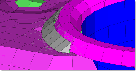
This specific type of realization is available in both the Spot and Seam panels, and uses 5-sided solid elements to more accurately represent the "bead" that results from welding. For spots, it produces individual welds; for seams, it produces a continuous weld.
|
Penta realizations also require two additional details: Depth (used by both Spot and Seam welds) and Width (used only by Spots). These parameters define how large the solid elements representing the weld are, in model units. When you select Penta (mig) from the type= field, additional entry fields display on the Spot or Seam panel to accept these values.
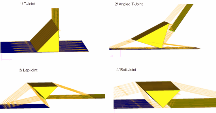
The penta element is usually placed on the side of the element sheet(s) closest to the connector icon. Engineering Solutions attempts to position the penta with its right angle pointing back at the element sheets as requested (except in the T junction case where the penta “points” towards the T intersection). T junctions, lap joints, and butt joints are supported.
In general the penta will not bleed through other elements. Penta realizations use an offset equal to 10% of the average component thickness to minimize such bleed-through. However, some bleed-through remains possible in some modeling situations.
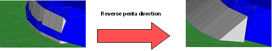
The penta seam functionality deals with curved lines, but if the pentas are not created in the required direction you can reverse the direction. This can be achieved automatically by either translating the seam connector into the correct quadrant for projections, or (in the case of Seam welds) by reversing the shell normals of one of the connecting components. The translation of the connector is the preferred method.
For any instances in which a Spot connector fails to realize, you should use the non-normal projections feature in the Spot panel – this feature allows the projections to capture more cases, but takes more processing. It does not need to be used all the time--only in cases where the connector fails to realize in the first attempt.
Penta realization is supported for shell-to-solid connections. However, some simple steps must be taken to allow this to happen:
| 1. | Create faces on the solid component and then organize the newly created shell elements (^faces) into the component collector that houses the 3D elements. You will now have a component collector housing both 2D and 3D elements. |
| 2. | Ensure that either the 2D normals are correct, or translate the connector to get the correct penta location and then realize the connector. The connector links must include the component with the 2D/3D elements and the shell component that you want the solids to connect to. |
| 3. | From the View menu, enable the Mask browser. In the browser, navigate to Components > Elements > 2D and click the isolate column for the entire 2D sub-folder (not any of the individual element types listed within it). Now only the 2D elements (faces) of the solid component display. |
| 4. | Delete the displayed faces. This leaves you with a connection attaching the solid elements to the shell component in question. |
This method ensures that the component links are preserved. If you try to connect directly to the ^faces component, when deleting the ^faces component the connector will unrealize because a component link has been removed. The above method bypasses the last point.