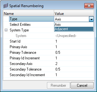
Renumbering can be done based on the local system direction or element adjacency.
Using this method you will renumber the rectangular regular array of elements or quads in two perpendicular directions in a user defined coordinate system (Cartesian or cylindrical). A local coordinate system must be created to match the two primary numbering directions.
| 1. | Select a list of nodes or elements to be renumbered. |
| 2. | Select the local system. The global system ID=0 cannot be used. |
| 3. | In the Start Id field enter an ID that is larger than the existing IDs in the database. |
| 4. | Provide the primary axis, tolerance and ID increment. |
| 5. | Provide the secondary axis, tolerance and ID increment. |
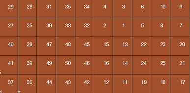
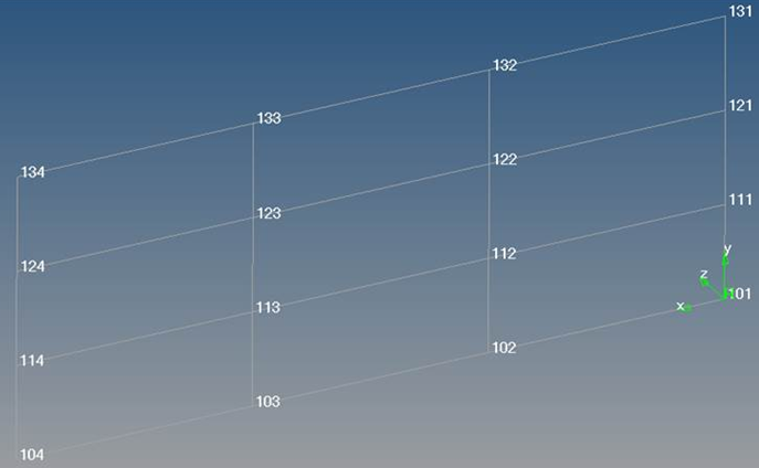
Before element renumber
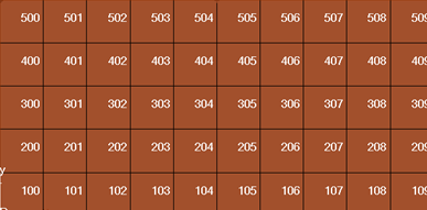
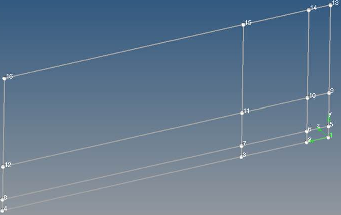
After element renumber: X increment by 1, Y increment by 100
|
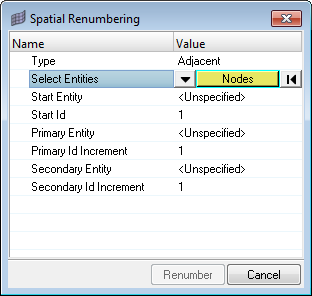
The element and node renumbering option is based on element/node connectivity directions instead of local system directions.
Using this method you must select the start element (or node) and the adjacent connected elements (or nodes) to indicate primary and secondary directions. These elements need to be connected. This method works only with quadrilateral elements (without any triangular elements) and should have a mapped (regular) pattern.
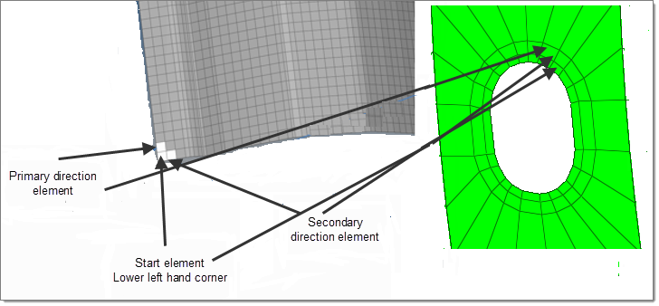
Adjacency based renumber
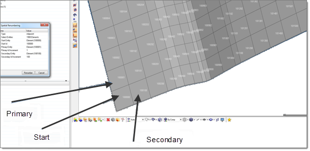
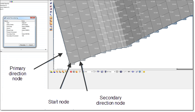
| 1. | Select Adjacent as the Type. |
| 2. | Select Nodes or Elements for the entity and enter the Start Id. |
| 3. | Select the primary direction element/node and the ID offset. This should be connected to the starting element. |
| 4. | Select the secondary direction element/node and the ID offset. This should also be connected to the starting element.
|
Element renumber
Node renumber
|
The tolerance is used to group the nodes/elements in the correct order for renumbering. For example, if you have a simple structured mesh with nodes distanced 5 mm on the local X direction and 2 mm on the local Y you want to renumber the nodes so that it starts with 101 for the starting ID. Then increment in local X direction by 1 (for example 101, 101+1, 101+2, and so on) and in local Y direction by 10 (for example 101, 101+10, 101+20, and so on).
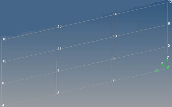
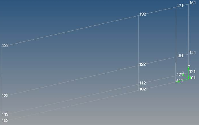
If you use the correct tolerance of 1 mm (which is <5 mm and < 2 mm nodal distances) here is the result:
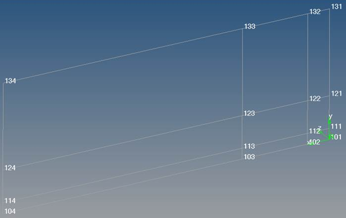
In a real scenario you rarely get meshes like the example above, so the distances between nodes are variable like the image below. You want to renumber it with the same objective and tolerances (1mm).
The result is:
As you can see in the image above the renumbering is not done properly. This is because the smallest nodal distance is 0.5 mm which is smaller than 1 mm tolerance. If you reduce the tolerance to 0.1 mm you will get the correct result.
|
See Also:
Aerospace Menu