|
»Click here to display Table of Contents«
|

Solid Map Meshing |

|

|

|

|
|
Solid Map Meshing |
|
|
|

|
|
»Click here to display Table of Contents«
|
Solid Map Meshing |
|
|
|
|
|
Solid Map Meshing |
|
|
|
|
In solid meshing, the ability to be meshed is referred to as mappability. Mappability is directional and can be likened to putting a surface mesh on one face of the solid, then extending that mesh along a vector through the solid volume. So, for example, a perfect cylinder is mappable in one direction (the axis between its top and bottom faces) while a perfect cube is mappable in three (the axes between each pair of its identical faces). However, a combustion engine's cylinder head consisting of two cylinders of different radius joined together into a single solid entity would need to be partitioned to divide the two cylinders. Once partitioned, each cylinder would become mappable in one direction.
Any given volume can have one of four states, which are color-coded when using the mappable view option on the Visualization toolbar. Although the colors can be customized, the default settings are:
| • | Blue indicates a solid that has not been edited at all and therefore is not evaluated for mappability. |
| • | Orange indicates a solid that has been edited, but remains completely unmappable (further partitioning may enable mapping). |
| • | Yellow indicates a solid that is mappable in 1 direction. |
| • | Green indicates a solid that is mappable in three directions (this is very rare). |
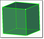
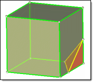
The first cube is mappable in 3 directions, but if a corner is split off it becomes
mappable in only 1 direction--and the corner is not mappable without further partitioning.
The Solid Map panel is used for solid-map meshing, and this panel includes several subpanels. The general, line drag, linear solid, and ends only subpanels all draw from the same set of input controls (the more specialized panels simply filter out the controls that do not apply to their mapping techniques).
| • | Use the general subpanel to access all of the possible entry controls for maximum flexibility. |
| • | Use the line drag subpanel to select a 2D mesh, and then select a line from the model geometry to use as the mapping direction. |
| • | Use the linear solid subpanel to select two existing 2D meshes and extrapolate a 3D mesh that connects them. |
| • | Use the ends only subpanel to select two opposing surfaces and one 2D mesh, then extrapolate the mesh between the surfaces. |
| • | Use the one volume subpanel to select a single mappable solid volume and create a new 3D mesh for it. |
| • | Use the multi solids subpanel to select multiple mappable solids and create 3D meshes for them. |
|
You can select multiple solids for solid map meshing provided that each individual solid is in fact mappable. However, the meshing engine cannot always mesh every selected solid in a single operation, even when all the selected solids display as mappable. This may happen if the mappable constraints from different solids within the selection contradict each other. For example, one type of mappable constraint is that certain surfaces (along faces) of a mappable solid must be of the map-mesh type. When such constraints are in conflict, faces that caused meshing to fail are marked with a red square icon:
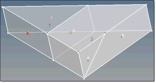
In this example both solids can be map-meshed individually, but solid #1 (the triangular one) must have all of the marked faces (5, 6, and 9) map-meshed. This, however, causes a conflict for solid #2, which can only be map-meshed by using the shared surface (6) as a destination. This conflicts since this shared surface must match the meshes on surfaces 4 and 8 in order to mesh solid #2.
In such a case, you can mesh the remaining solids by deselecting the ones that are marked with the red icon but retaining the others in your selection. This either allows you to mesh the unmarked solids in a single action, or helps you further diagnose the problem. The remaining solids, unfortunately, will require individual meshing or further partitioning before they can be solid-map meshed as a group.
See Also:
Partitioning Solids for Mappability