In this tutorial, you will learn how to:
| • | Weld between geometry surfaces and shell elements |
| • | Weld using a master connectors file and duplicating and reflecting connectors |
| • | Create connectors from existing welds to create new welds of a different type |
| • | Understand why connectors may fail to realize and how to correct the problems |
Tools
The Connectors module can be accessed by:
| • | The Connector Browser which can be opened using View > Connector Browsers |
Model Files
This tutorial uses the following file, which can be found in <hm.zip>/interfaces/lsdyna/. Copy the file(s) from this directory to your working directory.
Exercises
This tutorial contains the following exercises:
Exercise 1: Weld Between Geometry Surfaces and Shell Elements
Exercise 2: Weld Using a Master Connectors File and Duplicating and Reflecting Connectors
Exercise 3: Create Connectors from Existing Welds to Create New Welds of a Different Type
Exercise 4: Swap Welded Part
Exercise 5: Troubleshoot Failure of Connectors to Realize
The first four exercises will help you become familiar with connecting (welding) an assembly of parts, using various methods, and replacing parts with newer, similar parts and updating their affected connections. The fifth exercise will help you become familiar with troubleshooting failure of connectors to realize.
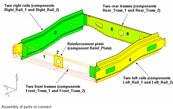
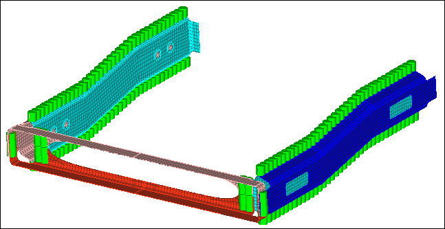
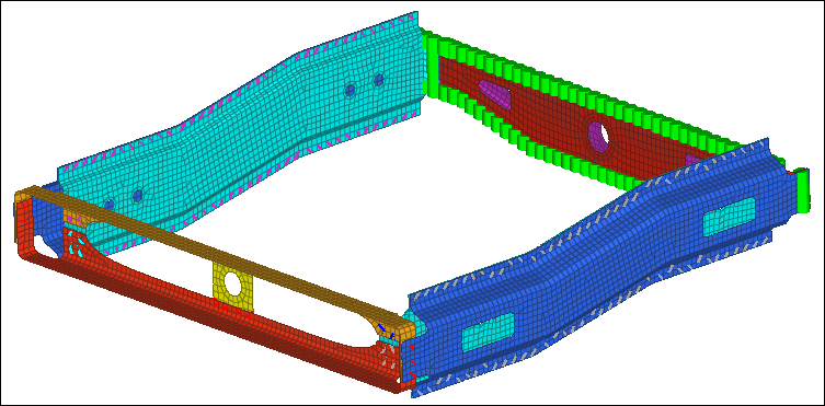
The part assembly used in the first four exercises is depicted in the image below. A very brief description of the corresponding exercises follows. (The exercises are independent of each other.)
Exercise 1: Weld Between Geometry Surfaces and Shell Elements
The purpose of this exercise is to become familiar with creating welds at pre-defined weld points between geometry surfaces and shell elements.
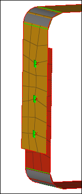
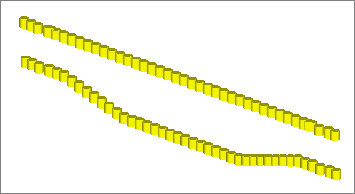
In this exercise, first weld the two front trusses depicted in the image below. To do this: 1) create connectors between their geometry surfaces at pre-defined weld points, and 2) realize the connectors into two node weld elements.
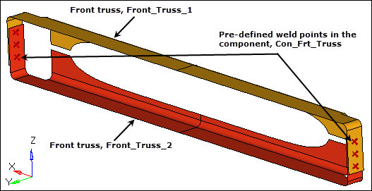
Weld the two front trusses
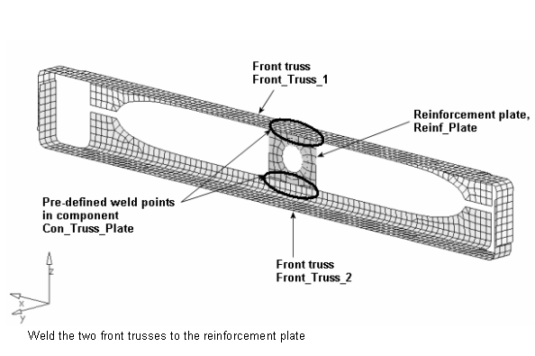
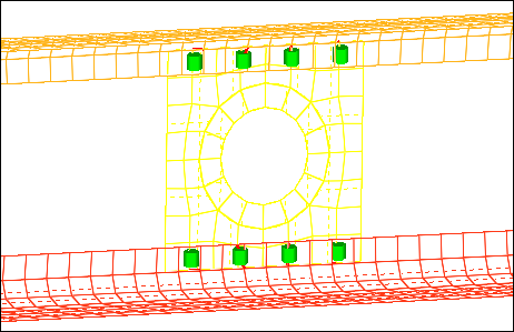
Second, weld the two front trusses to the reinforcement plate depicted in the image below. To do this: 1) create connectors between their shell elements at pre-defined weld points and, 2) realize the connectors into two node weld elements.
Step 1: Retrieve and view the model file
| 1. | Start HyperMesh Desktop. |
| 2. | In the User Profile dialog, set the user profile to LsDyna. |
| 3. | Open a model file by clicking File > Open > Model from the menu bar, or clicking  on the Standard toolbar. on the Standard toolbar. |
| 4. | In the Open Model dialog, open the frame_assembly_1.hm file. |
| 5. | On the Visualization toolbar, click  to shade your model's geometry and surface edges. to shade your model's geometry and surface edges. |
| 6. | Observe the model using various visual options available in HyperMesh (rotation, zooming, and so on). |
Step 2: Create welds between the geometry for the two front trusses at the pre-defined weld points
| 1. | Open the connector Spot panel by clicking Connectors > Create > Spots from the menu bar. |
| 2. | In the Model browser, verify that the current component is Con_Frt_Truss. |
| Hint: | The current component is always boldfaced in the Model browser, Component folder. |
| 3. | Set the location selector to points. |
| 4. | Select the six pre-defined weld points by clicking points >> by collectors. |
| 5. | Select the component, Con_Frt_Truss. |
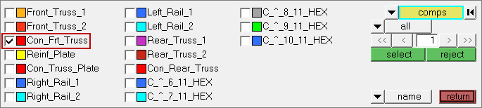
| 7. | Double-click connect what: comps. |
| 8. | Select the components, Front_Truss_1 and Front_Truss_2. |
| 10. | In the tolerance= field, enter 5. |
| 11. | Click type= and select weld. |
| 12. | Under the connect what selector, toggle from elems to geom. |
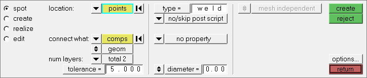
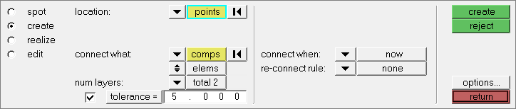
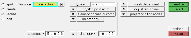
Settings for steps 2.3 through 2.12.
| 13. | Click create. HyperMesh creates and realizes six spot connectors, and organizes them as geometry (not elements) in the current component collector, Con_Frt_Truss. |
| Note: | A green connector indicates that the creation of the weld entity was successful. There are three states of connectors: realized (green ), unrealized (yellow ), unrealized (yellow  ), and failed (red ), and failed (red ). The color of the connectors can change from yellow to green (if created manually), indicating they are realized into weld elements. If you create connectors automatically, they will be green immediately as there is no interim unrealized (yellow) state. ). The color of the connectors can change from yellow to green (if created manually), indicating they are realized into weld elements. If you create connectors automatically, they will be green immediately as there is no interim unrealized (yellow) state. |
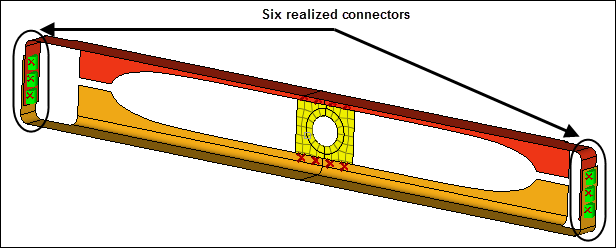
New connectors connecting the front truss components.
HyperMesh also adds fixed points to the surfaces at the ends of the weld elements to guarantee connectivity between the weld elements and the shell mesh that will be created on the surfaces.
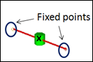
Weld element with fixed points created on the surfaces.
Step 3: Create a shell mesh on the two front truss components
| 1. | Open the Automesh panel by clicking Mesh > Create > 2D Automesh from the menu bar, or pressing F12. |
| 2. | Go to the size and bias subpanel. |
| 3. | Click surfs >> by collector. |
| 4. | Select the components, Front_Truss_1 and Front_Truss_2. |
| 6. | In the elem size= field, enter 10. |
| 7. | Set the mesh type to mixed. |
| 8. | Set the elems to surf comp/elems to current comp toggle to elems to surf comp. |
| 9. | Switch the mesh mode from interactive to automatic. |
| 10. | Click mesh. HyperMesh meshes the surfaces. |
| 11. | On the 3D View Controls toolbar, left-click on  to zoom into the area with a connector. See how the fixed point created from the weld has ensured the mesh seeding passes through the weld. to zoom into the area with a connector. See how the fixed point created from the weld has ensured the mesh seeding passes through the weld. |
Step 4: Create connectors between the shell mesh for the front trusses and the reinforcement plate at pre-defined points
In this step you will create and realize the connectors manually.
| 1. | In the Model browser, Component folder, right-click on Con_Truss_Plate and select Make Current from the context menu. |
| 2. | Open the connector Spot panel. |
| 3. | Go to the create subpanel. |
| 4. | Set the location selector to points. |
| 5. | Click points >> by collector. |
| 6. | Select the component, Con_Truss_Plate. |
| 8. | Set connect when to now. |
| 9. | Double-click connect what: comps. |
| 10. | Select the components: Front_Truss_1, Front_Truss_2, and Reinf_Plate. |
| 12. | Under the connect what selector, toggle from geom to elems. |
Settings for steps 4.4 through 4.12.
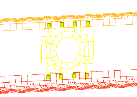
| 13. | Click create. HyperMesh creates eight spot connectors at the selected weld points, and organizes them into the current component collector, Con_Truss_Plate. |
Step 5: Realize the connectors in the component Con_Truss_Plate into weld elements
| 1. | Go to the realize subpanel. |
| 2. | Click location: connectors >> by collector. |
| 3. | Select the component, Con_Truss_Plate. |
| 5. | Click type= and select weld. |
| 6. | In the tolerance= field, enter 5. |
| 7. | Set the mesh independent/mesh dependent toggle to mesh dependent. |
| Note: | When mesh dependent is active, HyperMesh equivalences the nodes if the realized finite element of the connector is coincident to a node of the shell mesh it is being connected to. If there are no suitable nodes present, this option partitions the mesh accordingly to ensure the mesh seeding passes through the weld point. |
| 8. | Click realize. HyperMesh realizes the selected connectors into weld elements. |
Step 6 (Optional): Save your work
The exercise is complete. Save your work as a HyperMesh file.
Exercise 2: Weld Using a Master Connectors File and Duplicating and Reflecting Connectors
The purpose of this exercise is to become familiar with:
| • | Defining weld locations in HyperMesh by importing a master connectors file. |
| • | Duplicating, reflecting, and updating connectors to create welds. |
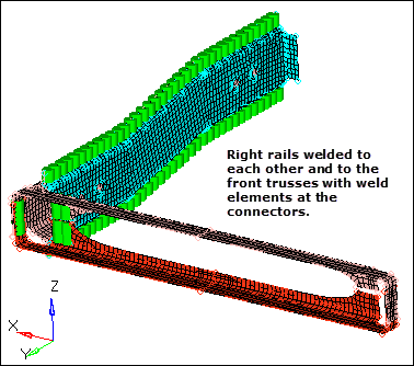
In this exercise, you will first weld the two right rails to each other and to the two front trusses depicted in the image below. To do this: 1) import weld point data from a master connectors file, 2) create connectors, and 3) realize the connectors into LS-DYNA 100 Mat100 (beam) welds.
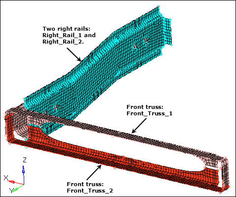
Weld the two right rails to each other and to the front trusses.
Second, you will weld the two left rails to each other and to the two front trusses depicted in the image below. To do this: 1) duplicate and reflect the connectors that were created by importing the master connectors file, 2) update the link information for the reflected connectors, and 3) realize the connectors into LS-DYNA 100 Mat100 (beam) welds.
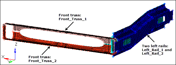
Weld the two left rails to each other and to the two front trusses.
Third, you will combine adjacent 2T connectors into 3T connectors in order to update adjacent 2T welds to 3T welds.
Step 1: Retrieve and view the model file
| 1. | Start HyperMesh Desktop. |
| 2. | In the User Profile dialog, set the user profile to LsDyna. |
| 3. | Open a model file by clicking File > Open > Model from the menu bar, or clicking on the Standard toolbar. |
| 4. | In the Open Model dialog, open the frame_assembly_2.hm file. |
| 5. | Observe the model using various visual options available in HyperMesh (rotation, zooming, and so on). |
Step 2: Create connectors to connect the right rails to each other and to the front trusses by importing a master connectors file
| 1. | From the menu bar, click File > Import > Connectors. |
| 2. | Set File type to Connectors |
| 3. | In the File field, open the rails_frt_truss.mwf file. |
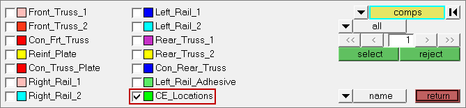
| 4. | Click Import. HyperMesh imports the connectors from the file, and organizes them into a new component, CE_Locations. |
Step 3: Realize the connectors in the component, CE_Locations, into LS-DYNA 100 Mat100 (beam) welds
| 1. | In the Model browser, Component folder, right-click on CE_Locations and select Make Current from the context menu. |
| 2. | Open the connector Spot panel, realize subpanel by clicking Connectors > Realize > Spots from the menu bar. |
| 3. | Click location: connectors >> by collector. |
| 4. | Select the component, CE_Locations. |
| 6. | In the tolerance = field, enter 5. |
| 7. | Set the mesh independent/mesh dependent toggle to mesh independent. |
| 8. | Click type = and select mat100. |
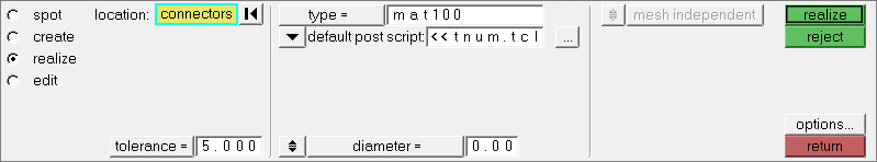
Settings for steps 3.3 through 3.8.
| 9. | Click realize. HyperMesh realizes the selected connectors into LS-DYNA 100 Mat100 (beam) welds, and organizes them into the following new component collectors: |
| Note: | The naming convention for these components is C_^_[id of comp 1]_[id of comp 2]. |
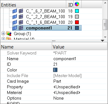
Step 4: Verify materials were automatically created when the LS-DYNA 100 Mat100 (beam) welds were created
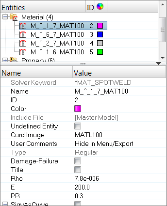
| 1. | In the Model browser, Material folder, review the materials with IDs 2 through 5, that were created when the LS-DYNA 100 Mat100 (beam) welds were created. |
| Note: | The naming convention for them is M_^_[id of comp 1]_[id of comp 2]. One material is created for every two components that are connected. |
| 2. | Select one of the materials with IDs 2 through 5. The Entity Editor opens and displays the material's card details. |
| Note: | The solver keyword is set to *MAT_SPOTWELD, and the values are automatically specified for the density, Young’s Modulus, and Poisson’s Ratio parameters. |
Step 5: Verify that properties were automatically created when the LS-DYNA 100 Mat100 (beam) welds were created
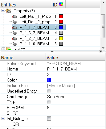
| 1. | In the Model browser, Property folder, review the properties with IDs 1 through 6, that were created when the LS-DYNA 100 Mat100 (beam) welds were created. |
| Note: | The naming convention for them is P_^_[id of comp 1]_[id of comp 2]. One property is created for every two components that are connected. |
| 2. | Select one of the properties with IDs 1 through 6. The Entity Editor opens and displays the property's card details. |
| Note: | The solver keyword is set to *SECTION_BEAM, and the default values are specified for the property’s parameters. |
Step 6: Verify that a contact was automatically created when the LS-DYNA 100 Mat100 (beam) welds were created
| 1. | In the Model browser, Group folder, click C_Contact_Spotweld_1. The Entity Editor opens and displays the group's card details. |
| Note: | The solver keyword is set to *CONTACT_SPOTWELD_ID. |
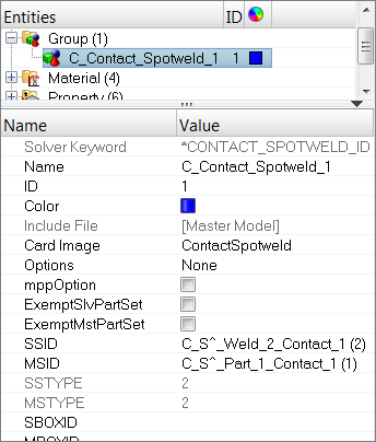
| 2. | Open the Interfaces panel by clicking BCs > Assign > Interface Entities from the menu bar. |
| 3. | In the panel area, click name= and select C_Contact_Spotweld_1. |
| 4. | Review the contacts by clicking review. The contact’s master elements temporarily display blue, and its slave elements temporarily display red. |
Step 7: Display the components Left_Rail_1 and Left_Rail_2 for elements
| 1. | In the Model browser, Component folder, right-click on Left_Rail_1 and Left_Rail_2 and select Show from the context menu. The components display in the graphics area. |
| Tip: | Select multiple components by pressing CTRL while left-clicking on the components. |
Step 8: Duplicate the connectors created from the master connectors file and reflect them
| 1. | In the Model browser, right-click and select Create > Component from the context menu. A new component opens in the Entity Editor. |
| 2. | For Name, enter CE_Locations_Dup. |
| Note: | You do not need to assign any materials or properties. |
| 3. | Open the Reflect panel by clicking Connectors > Reflect > Connectors from the menu bar. |
| 4. | Click connectors >> by collector. |
| 5. | Select the component, CE_Locations. |
| 7. | Click connectors >> duplicate >> current comp. HyperMesh duplicates the displayed connectors, are organizes them into the current component, CE_Locations_Dup. |
| 8. | Set the orientation selector to x-axis. |
| Note: | This is the axis normal to the plane of interest. |
| 9. | Reflect about the base node by clicking  . . |
| 10. | Click x =. HyperMesh activates the x =, y =, and z = fields. |
| Note: | By default their values are 0.000, which is the base point you want to reflect about. |
| 12. | Click reflect. HyperMesh reflects the connectors. |
Step 9: Update the connectors for the left rails to link them to the left rail components
| 1. | Open the Connector browser by clicking View > Browsers > HyperMesh > Connector from the menu bar. |
| 2. | In the Connector Entity browser, expand the mat 100 folder, which contains the connectors in the model with material mat100. |
| Note: | The reflected connectors are displayed in yellow, which indicates that they are unrealized. |
| 3. | Select all of the unrealized connectors in the list. |
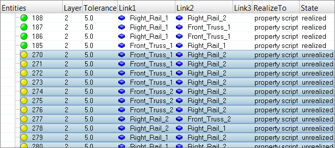
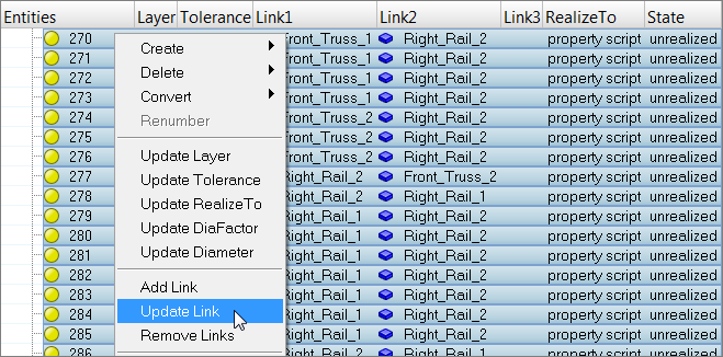
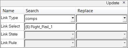
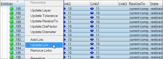
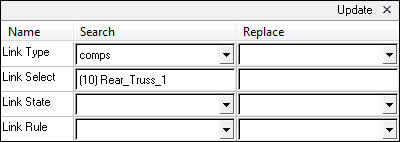
| 4. | In the Entities column, right-click on the selected connectors and select Update Link from the context menu. The Update window opens. |
| 5. | In the Search column, set the Link Type to comps. |
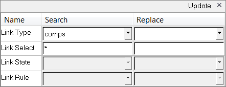
| 6. | In the Search column, click the Link Select field. |
| 7. | In the panel area, click component. |
| 8. | Select the component, Right_Rail_1. |
| 9. | Click proceed. The Link Select field displays Right_Rail_1. |
| 10. | In the Replace column, set the Link Type to comps. |
| 11. | In the Replace column, click the Link Select field. |
| 12. | In the panel area, click component. |
| 13. | Select the component, Left_Rail_1. |
| 14. | Click proceed. The Link Select field displays Left_Rail_1. |
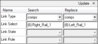
| 15. | Click Update. HyperMesh updates the connector's links. |
| 16. | Repeat 9.5 through 9.15, except search for the Right_Rail_2 component and replace it with the Left_Rail_2 component. |
| 17. | Scroll through the list of unrealized connectors to make sure that none of the connectors are linked to the right rail components. |
| 18. | Close the Update window by clicking X next to Update. |
| 19. | Right-click on the selected connectors and select Rerealize from the context menu. HyperMesh realizes the connectors. |
Step 10: Verify that all connectors are realized and identify the pairs of adjacent connectors
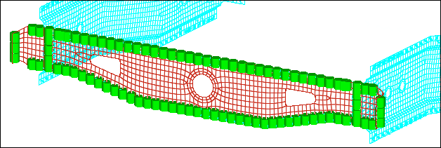
All of the connectors listed in the Connector Entity browser are displayed in green in the State column, which indicates that they are realized.
| 1. | Zoom into one of the two areas where the front trusses are connected to the rail components. |
| Note: | In these two areas, pairs of adjacent connectors exist. |
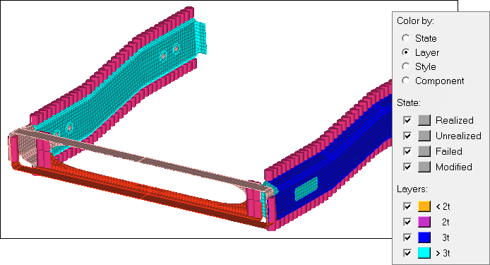
| 2. | On the Visualization toolbar, click  . . |
| 3. | In the Visualization tab, click  . . |
| 4. | Under Color by, select Layer. HyperMesh changes the connectors color to purple because under Layers, 2t (two thickness) is defined by the color purple. |
| Note: | This option indicates that each of these connectors link two components. Because each pair of connectors creates a series of two weld elements, you can combine each pair into a single connector, which links the three components together. |
Step 11: Isolate the pairs of adjacent, 2t connectors identified in the previous step
| 1. | In the Model browser, turn off the geometry display for all of the components. |
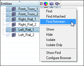
| 2. | In the Connector browser, Link Entity browser, while pressing CTRL, select Front_Truss_1, Front_Truss_2, Right_Rail_1, and Left_Rail_1. |
| 3. | Right-click and select Find Between from the context menu. HyperMesh finds and displays the connectors between the four components you selected. |
Step 12: Unrealize the selected connectors
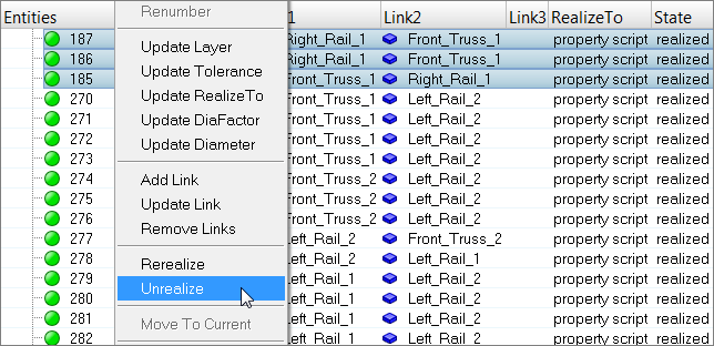
The connectors you found in the previous step should still be selected in the Connector Entity browser.
| 1. | In the Connector Entity browser, right-click on the selected connectors and select Unrealize from the context menu. |
Step 13 (Optional): Save your work
The exercise is complete. Save your work as a HyperMesh file.
Exercise 3: Create Connectors from Existing Welds to Create New Welds of a Different Type
The purpose of this exercise is to become familiar with absorbing existing finite element welds into connectors in order to create new finite element welds of a different type.
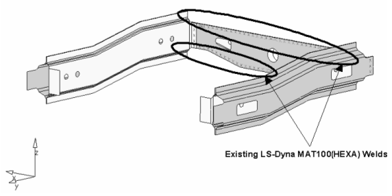
In this exercise, LS-DYNA 101 Mat100 (hexa) welds already connect the rear trusses to each other. You will first update the weld type to LS-DYNA 100 Mat100 (beam) welds. To do this: 1) create connectors from the existing LS-DYNA 101 Mat100 (hexa) welds, and 2) realize the connectors into LS-DYNA 100 Mat100 (beam) welds.
Second, you will update the existing LS-DYNA 101 MAT100 (hexa) welds to LS-DYNA 100 Mat100 (beam) welds.
Step 1: Retrieve and view the model file
| 1. | Start HyperMesh Desktop. |
| 2. | In the User Profile dialog, set the user profile to LsDyna. |
| 3. | Open a model file by clicking File > Open > Model from the menu bar, or clicking on the Standard toolbar. |
| 4. | In the Open Model dialog, open the frame_assembly_3.hm file. |
| 5. | Observe the model using various visual options available in HyperMesh (rotation, zooming, and so on). |
Step 2: Create connectors from existing LS-DYNA 101 Mat100 (hexa) welds
| 1. | From the menu bar, click Connectors > Fe Absorb. |
| 2. | In the Automated Connector Creation and FE Absorption dialog, set FE configs to custom. |
| 3. | Set FE type to dyna 101 mat 100 (hexa). |
| 4. | Set the Elem filter toggle to select. |
| 5. | Double-click the Elem filter: Elements selector. |
| 6. | In the panel area, click elems >> by collector. |
| 7. | Select the following components: |
| 9. | Click proceed to return to the dialog. |
| 10. | Set FE connectivity to Mesh independent (projs). |
| 11. | Select the Move connectors to FE component checkbox. |
| 12. | Click Absorb. HyperMesh absorbs the elements into connectors at the locations of the LS-DYNA 101Mat100 (hexa) welds, and organizes them into the respective components to which the LS-DYNA 101 Mat100 (hexa) welds belong. |
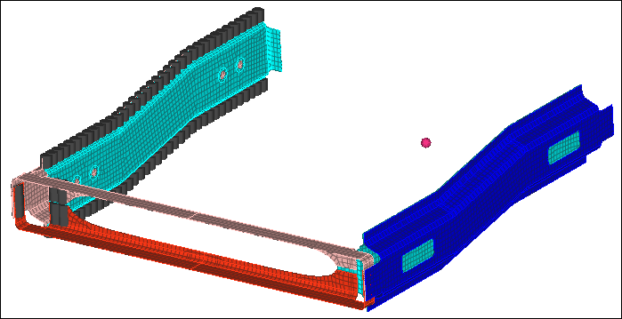
Step 3: Isolate the 2t connectors between the Rear_Truss_2 component and the Right_Rail_2 and Left_Rail_2 components
| 1. | Open the Connector browser by clicking View > Browsers > HyperMesh > Connector from the menu bar. |
| 2. | In the Link Entity browser, while pressing CTRL, select Rear_Truss_2, Right_Rail_2, and Left_Rail_2. |
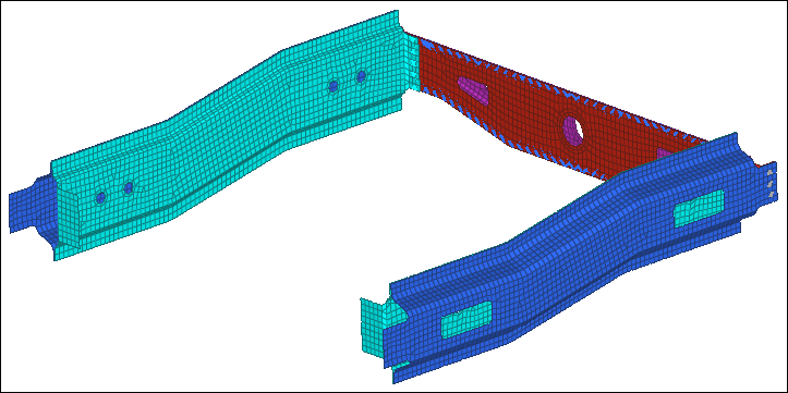
| 3. | Right-click and select Find Between from the context menu. HyperMesh finds and displays ten connectors between the three components you selected. |
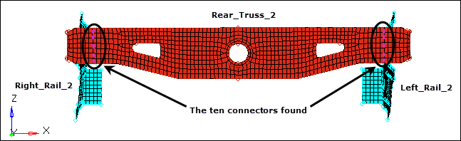
Connectors found between the Rear_Truss_2, Left_Rail_2, and Right_Rail_2 components.
Step 4: Add Rear_Truss_1 as a third link to four of the ten displayed 2t connectors
| 1. | In the Model browser, Component folder, while pressing CTRL, select Rear_Truss_2, Left_Rail_2 and Right_Rail_2 . |
| 2. | Right-click on the selected components and select Show from the context menu. |
| 3. | Turn on the geometry display for the component C^9_11_HEX. |
| 4. | Open the Add Links panel by clicking Connectors > Assign > Links from the menu bar. |
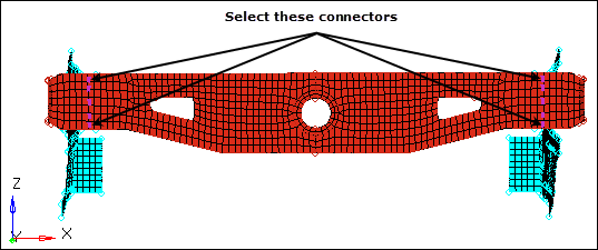
| 5. | Activate the location: connectors selector. |
| 6. | Select the four connectors indicated in the following image. |
| 7. | Set the connect what selector to comps. |
| 9. | Select the component, Rear_Truss_1. |
| 11. | Set the connect what toggle to elems. |
| 12. | Select the checkbox next to search tol =. |
| 13. | In the search tol= filed, enter 5. |
| 14. | Set # of layers to total 3. |
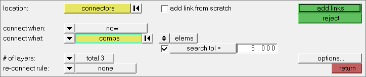
Settings for steps 4.5 through 4.14.
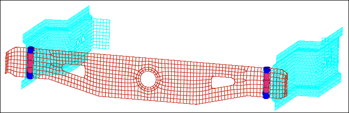
| 15. | Click add links. HyperMesh updates the connector's definitions, and changes their display color to blue, as they are now 3t connections. |
Step 5: Unrealize the connectors for the LS-DYNA 101 Mat100 (hexa) welds
| 1. | In the Model browser, turn on the geometry display for the following components only: |
| 2. | Open the Unrealize panel by clicking Connectors > Unrealize from the menu bar. |
| 3. | Click connectors >> displayed. |
| 4. | Click unrealize. HyperMesh unrealizes the connectors, and deletes the weld elements associated to these connectors. |
| 6. | On the Visualization toolbar, click . |
| 7. | In the Visualization tab, click . |
| 8. | Under Color by, select State. HyperMesh displays the connectors in yellow, which indicates that they are not realized into FE elements. |
Step 6: Realize the unrealized connectors into LS-DYNA 100 Mat100 (beam) welds
| 1. | Open the connector Spot panel, realize subpanel by clicking Connectors > Realize > Spots from the menu bar. |
| 2. | Click location: connectors >> displayed. |
| 3. | Click type= and select mat 100. |
| 4. | In the tolerance =, enter 5. |
| 5. | Click realize. HyperMesh realizes the connectors. |
Step 7 (Optional): Save your work
The exercise is complete. Save your work as a HyperMesh file.
Exercise 4: Swap Welded Part
The purpose of this exercise is to become familiar with swapping welded parts and updating their affected connections (welds).
In this exercise, you will replace the component Rear_Truss_1 with a new, similar part and update its affected connections (welds). To do this: 1) update the connectors to use the "use name" rule, 2) delete the old part, 3) import the new part, and 4) realize the corresponding connectors into LS-DYNA 100 Mat100 (beam) welds.
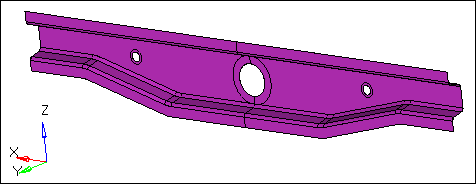
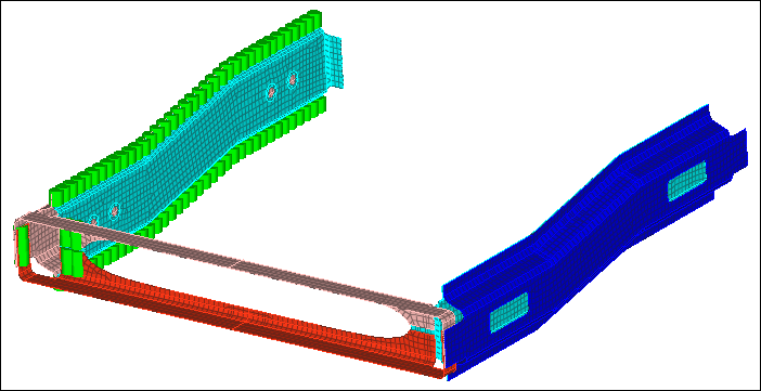
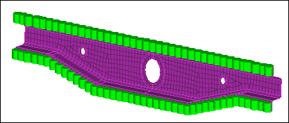
This part (Rear_Truss_1 component) will be swapped.
Step 1: Open the model file
| 1. | Start HyperMesh Desktop. |
| 2. | In the User Profile dialog, set the user profile to LsDyna. |
| 3. | Open a model file by clicking File > Open > Model from the menu bar, or clicking on the Standard toolbar. |
| 4. | In the Open Model dialog, open the frame_assembly_4.hm file. |
| 5. | Observe the model using various visual options available in HyperMesh (rotation, zooming, and so on). |
Step 2: Import the new model and update the connectors to use the rule "use name" when reconnecting parts
| 1. | Open the Connector browser by clicking View > Browsers > HyperMesh > Connector from the menu bar. |
| 2. | In the Connector Entity browser, right-click and select Configure Browser from the context menu. |
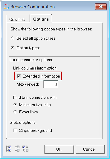
| 3. | In the Browser Configuration dialog, click the Options tab. |
| 4. | Under Local connector options, select the Extended information checkbox. |
| Note: | This option allows you to edit connector attributes. |
| 6. | From the menu bar, click File > Import > Model. |
| 7. | In the Import tab, click  . . |
| 8. | In the Open dialog, navigate to your working directory and open the rear_truss_1_new.hm file. |
| 10. | In the Link Entity browser, right-click on Rear_Truss_1 and select Find from the context menu. HyperMesh isolates the component Rear_Truss_1 and the connectors attached to it in the graphics area. Also, HyperMesh highlights the corresponding connectors in the Connector Entity browser. |
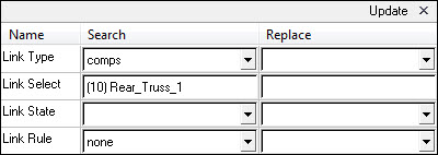
| 11. | In the Connector Entity browser, right-click on the selected connectors and select Update Link from the context menu. |
| 12. | In the Update window, Search column, click the Link Select field. |
| 13. | In the panel area, click component. |
| 14. | Select the component, Rear_Truss_1. |
| 15. | Click proceed. The Link Select field displays Rear_Truss_1. |
| 16. | In the Search column, set Link Rule to none. |
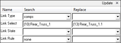
| 17. | In the Replace column, click the Link Select field. |
| 18. | In the panel area, click component. |
| 19. | Select the component, Rear_Truss_1.1. |
| 20. | Click proceed. The Link Select field displays Rear_Truss_1.1. |
| 21. | In the Replace column, set Link Rule to use-name. |
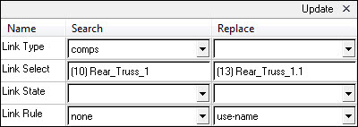
| 22. | Click Update. HyperMesh updates the connector links. |
| 23. | Close the Update window by clicking X next to Update. |
Step 3: Delete the component Rear_Truss_1
| 1. | Open the Delete panel by pressing F2. |
| 2. | Set the entity selector to comps. |
| 4. | Select the component, Rear_Truss_1. |
| 6. | Click delete entity. The display color of the connectors associated to the deleted component changes from green (realized state) to yellow (unrealized state), because the deleted component was one of the connectors’ links. Also, HyperMesh deletes the existing finite element welds. |
Step 4: Realize the unrealized connectors
| 1. | Open the connector Spot panel, realize subpanel by clicking Connectors > Realize > Spots from the menu bar. |
| 2. | Click location: connectors >> displayed. |
| 3. | Click type= and select mat100. |
| 4. | In the tolerance =, enter 5. |
| 5. | Click realize. HyperMesh realizes the connectors. |
Step 5 (Optional): Save your work
The exercise is complete. Save your work as a HyperMesh file.
Exercise 5: Troubleshoot Failure of Connectors to Realize
The purpose of this exercise is to become familiar with troubleshooting the failure of connectors to realize. Specifically, this exercise will help you identify two common issues: 1) small projection tolerance and 2) missing link definitions.
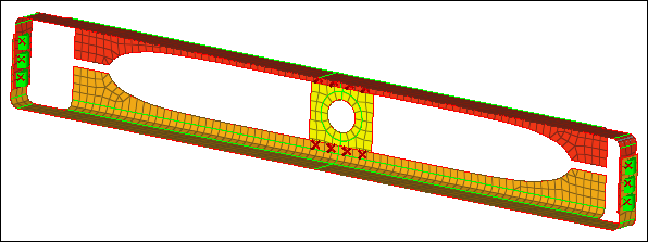
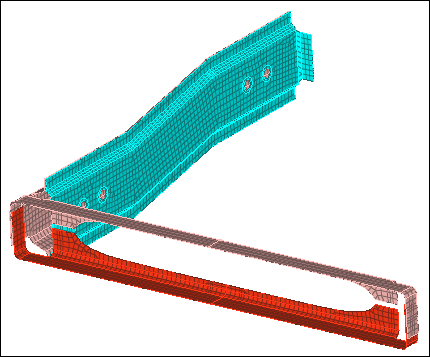
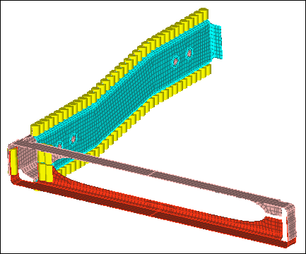
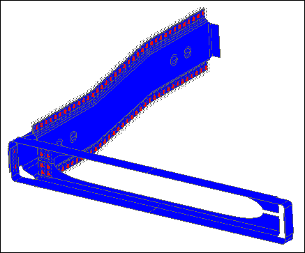
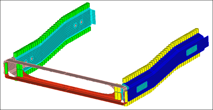
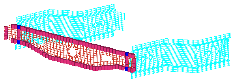
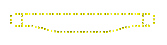
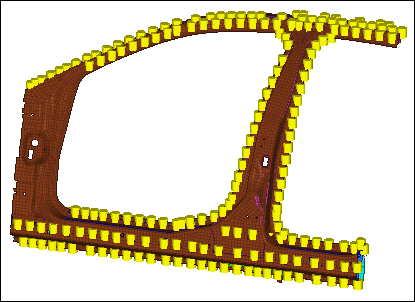
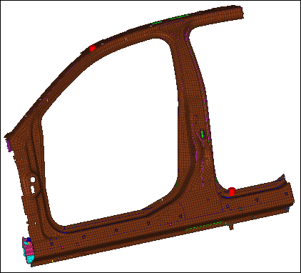
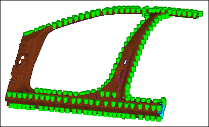
In this exercise, you will realize connectors to weld parts of a vehicle door frame. The model is depicted below.
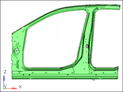
Vehicle door frame model
Step 1: Retrieve the HyperMesh file
| 1. | Start HyperMesh Desktop. |
| 2. | In the User Profile dialog, set the user profile to LsDyna. |
| 3. | Open a model file by clicking File > Open > Model from the menu bar, or clickin on the Standard toolbar. |
| 4. | In the Open Model dialog, open the body_side_assembly.hm file. |
| 5. | Observe the model using various visual options available in HyperMesh (rotation, zooming, and so on). |
Step 2: Realize all the connectors using a projection tolerance of 1.0
| 1. | Open the connector Spot panel, realize subpanel by clicking Connectors > Realize > Spots from the menu bar. |
| 2. | Click location: connectors >> all. |
| 3. | Click type = and select mat100 |
| 4. | In the tolerance =, enter 1.0 |
| 5. | Click realize. HyperMesh realizes the selected connectors into LS-DYNA 100 Mat100 (beam) welds. |
Note: The Status bar reads, "257 connectors realized (9 failed)".
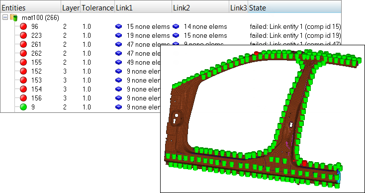
Step 3: Review the information table listing the connectors that failed to realize and determine the reasons for failure
| 1. | On the Visualization toolbar, click . |
| 2. | In the Visualization tab, click . |
| 3. | Under State, clear the Realized checkbox. The display of the realized (green) connectors turns off. |
| 4. | Open the Connector browser by clicking View > Browsers > HyperMesh > Connector from the menu bar. |
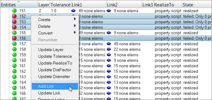
| 5. | In the Connector Entity browser, review the five connectors (with the IDs: 96, 155, 223, 261, and 262) that are red. |
| Note: | In the Layer column, 2 layers are specified, and in the Link1 and Link2 columns, a link is defined. Because the number of layers and links that were defined match, a possible cause for the connectors not realizing is a small projection tolerance. |
| 6. | Review the four connectors with the IDs 152, 153, 154, and 156. |
| Note: | In the Layer column, 3 layers are specified. In the Link1 column, one link is defined; in the Link2 and Link3 columns, no links are defined. Because the numbers of layers and links do not match, the likely cause for the connectors not realizing is undefined link definitions. |
Step 4: Realize the failed connectors using a larger projection tolerance
| 1. | In the Connector Entity browser, right-click and select Create > Spot from the context menu. |
| 2. | Click location: connectors >> displayed. |
| 3. | Click type = and select mat100 |
| 4. | In the tolerance =, enter 2.0 |
| 5. | Click realize. HyperMesh realizes the selected connectors into LS-DYNA 100 Mat100 (beam) welds. |
| Note: | The Status bar reads, "5 connectors realized (4 failed)". |
Step 5: Define the missing second link for the failed connectors
| 1. | In the Connector Entity browser, select the four red, unrealized connectors. |
| Tip: | Select multiple connectors by pressing CTRL while left-clicking on connectors. |
| 2. | Right-click on the selected connectors and select Add Link from the context menu. |
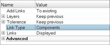
| 3. | In the Add Link window, set Link Type to Components. |
| 5. | Under Links, for Entities, click 0 Component >> comps. |
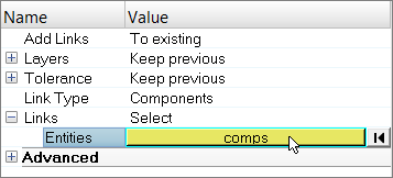
| 6. | In the panel area, click comps. |
| 7. | Select the component, Comp2. |
| 10. | At the top of the Add Links window, click Add. |
| 11. | In the confirm dialog, click Add Link. HyperMesh adds the specified link entity to the connector. |
Step 6: Define the missing third link for the failed connectors
| 1. | Repeat Step 5 above, except select Comp10 in step 5.7. |
Step 7: Realize the failed connectors
In this step you should still be in the Spot panel, realize subpanel.
| 1. | Click location: connectors >> displayed. |
| 2. | Click type = and select mat100 |
| 3. | In the tolerance =, enter 4.0 |
| 4. | Click realize. HyperMesh realizes the selected connectors into LS-DYNA 100 Mat100 (beam) welds. |
| 5. | On the Visualization toolbar, click . |
| 6. | In the Visualization tab, click . |
| 7. | Under Color by, select State. |
| 8. | Under State, select the Realized checkbox. HyperMesh displays all of the connectors, which are green. |
| Note: | All of the connectors are realized into FE elements. |
Step 8 (Optional): Save your work
The exercise is complete. Save your work as a HyperMesh file.
See Also:
HyperMesh Tutorials


