In this tutorial, you will learn how to:
| • | Define *ALE cards and other cards related to the LS-DYNA Arbitrary-Lagrangian-Eulerian (ALE) capability |
| • | Update the *SECTION card used by the ALE components INK and AIR to *SECTION_SOLID_ALE. |
| • | Define *EOS_LINEAR_POLYNOMIAL for the ALE components. |
| • | Define *INITIAL_VOID_PART to define the AIR component as the void in the fluid interaction. |
| • | Define *ALE_REFERENCE_SYSTEM_NODE to control the motion of the ALE mesh. |
| • | Define *ALE_REFERENCE_SYSTEM_GROUP to specify the reference system type for the fluid interaction of the ALE components. |
Tools
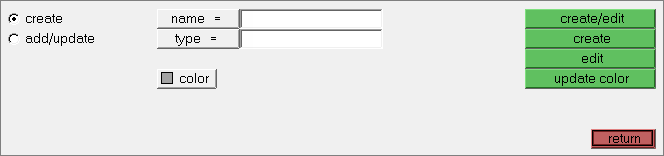
The ALE setup panel can be accessed from the Analysis page. Use the ALE setup panel to create and modify input data pertaining to the Arbitrary-Lagrangian Eulerian LS-DYNA capability.
The Card Edit feature can be accessed by clicking  on the Collectors toolbar. Use the Card Edit panel to select the entities that are viewed in the card image subpanel. The card images are defined in the template file.
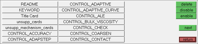
To access the control cards feature do one of the following:
| • | From the menu bar, click Setup > Create > Control Cards. |
| • | From the Analysis page, click control cards |
Use the Control Cards panel to set up job-level, solver specific data. The available control cards are defined in the template file.
Model Files
This tutorial uses the cartridge.hm file, which can be found in <hm.zip>/interfaces/lsdyna/. Copy the file(s) from this directory to your working directory.
Exercise: Define Model Data for the Ink Cartridge Drop Analysis
The purpose of this exercise is to help you become familiar with defining LS-DYNA cards related to the ALE capability. In this exercise you will set up the model data for an LS-DYNA analysis of an ink cartridge falling through air and onto the ground. The ink and ground model is shown in the image below.
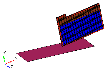
Ink cartridge model
Loads and contacts are already defined in the model as follows.
| • | A velocity along the negative Y-axis is applied to every node of the ink cartridge using the card *INITIAL_VELOCITY. |
| • | The interaction between the cartridge and the platform is defined using the card *CONTACT_AUTOMATIC_NODES_TO_SURFACE. All of the nodes of the CARTRIDGE are slave to the master PLATFORM component. |
| • | Single point constraints are applied throughout the model. The PLATFORM component has all of its DOFs fully locked, while the parts in the ink cartridge have the Z translation (DOF 3) constrained. This last constraint is necessary for symmetry reasons since the model has been simplified. |
| • | A gravity load along the negative Y direction is applied to the entire model. A curve defining the force versus time function is defined to fully create a gravity load. |
Step 1: Load the LS-DYNA profile
| 1. | Start HyperMesh Desktop. |
| 2. | In the User Profile dialog, set the user profile to LsDyna. |
Step 2: Retrieve the model file and review it’s contents
| 1. | Open a model file by clicking File > Open > Model from the menu bar, or clicking  on the Standard toolbar. on the Standard toolbar. |
| 2. | In the Open Model dialog, open the cartridge.hm file. The model appears in the graphics area. |
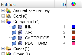
| 3. | In the Model browser, expand the Component folder. Notice the model is broken up into four component collectors: AIR, CARTRIDGE, INK, and PLATFORM. |
| 4. | Use the Model browser or the Solver browser to review the defined materials and properties. |
Step 3: Update the *SECTION_SOLID card used by the ALE components INK and AIR to *SECTION_SOLID_ALE
Method 1 - Using the Solver Browser
| 1. | Open the Solver browser by clicking View > Browsers > HyperMesh > Solver from the menu bar. |
| 2. | In the *SECTION > *SECTION_SOLID folder, click SOLID PROP FOR ALE. The Entity Editor opens, and displays the property's corresponding data. |
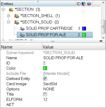
| 3. | For ELFORM (Element formulation options), verify that it is set to 12. |
Method 2 - Using the Model Browser
| 5. | In the Model browser, Property folder, click SOLID PROP FOR ALE. The Entity Editor opens, and displays the property's corresponding data. |
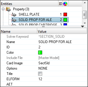
| 6. | For ELFORM (Element formulation options), verify that it is set to 12. |
| 7. | For Options, select ALE. |
Method 3 - Using the Card Editor
| 8. | In the Model or Solver browser, right-click on the property SOLID PROP FOR ALE and select Card Edit from the context menu. The Card Image dialog opens. |
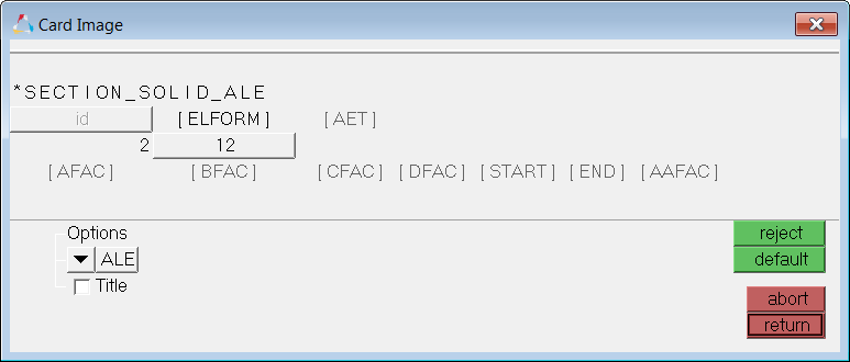
| 9. | For ELFORM (Element formulation options), verify that it is set to 12. |
| 10. | For Options, select ALE. |
Step 4: Define *EOS_LINEAR_POLYNOMIAL for the ALE components
| 1. | In the Solver browser, right-click and select Create > *EOS > *EOS_LINEAR_POLYNOMIAL from the context menu. A new property opens in the Entity Editor. |
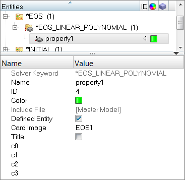
| 2. | For Name, enter EOS_LINEAR. |
| 3. | For c1 (1st polynomial equation coefficient), enter 1.5E+9. |
| 4. | For V0 (Initial relative volume), enter 1. |
Step 5: Assign *EOS_LINEAR_POLYNOMIAL for the ALE components
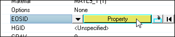
| 1. | In the Solver browser, *PART > *PART folder, and click INK. The Entity Editor opens, and displays the component's corresponding data. |
| 2. | For EOSID, click Unspecified >> Property. |
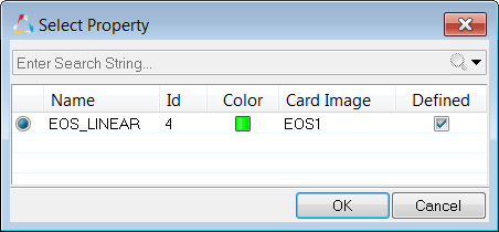
| 3. | In the Select Property dialog, select EOS_LINEAR and then click OK. |
| 4. | Repeat steps 1-3 for the AIR component. |
Step 6: Define *INITIAL_VOID_PART to define the AIR component as the void in the fluid interaction
| 1. | In the Solver browser, right-click and select Create > *INITIAL > *INITIAL_VOID from the context menu. A new group opens in the Entity Editor. |
| 3. | For PSID/PID, click 0 Components >> Components. |
| 4. | In the Select Components dialog, select AIR and then click OK. |
Step 7: Define *ALE_REFERENCE_SYSTEM_NODE to control the motion of the ALE mesh
| 1. | In the Solver browser, select Create > *ALE > *ALE_REFERENCE_SYSTEM_NODE from the context menu. A new group opens in the Entity Editor. |
| 2. | For Name, enter ALE_NODE. |
| 3. | For NodeCount, enter 3. |
| 4. | In the Data: NID row, click  . . |
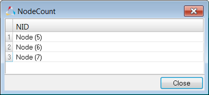
| 5. | In the NodeCount dialog, for NID(1), click Unspecified >> Node. |
| 6. | In the panel area, click node. |
| 7. | In the id= field, enter 5 and then press ENTER. |
| 9. | Repeat steps 7.5 through 7.8 for NID(2) and NID(3). For NID(2), select node 6; for NID(3), select node 7. |
Step 8: Define *ALE_REFERENCE_SYSTEM_GROUP to specify the reference system type for the fluid interaction of the ALE components
| 1. | In the Solver browser, select Create > *ALE > *ALE_REFERENCE_SYSTEM_GROUP from the context menu. A new group opens in the Entity Editor. |
| 2. | For Name, enter SYSTEM_GROUP. |
| 4. | Set the entity selector to Components. |
| 6. | In the Select Components dialog, select INK and AIR. |
| 10. | In the Select Group dialog, select ALE_NODE and then click OK. |
Step 9: Review the pre-defined *CONTROL_ALE card and export the model to an LS-DYNA 971 formatted input file
| 1. | In the Solver browser, *CONTROL > *CONTROL_ALE folder, click *ALE1. The Entity Editor opens, and displays the control card's corresponding data. |
| 2. | Review the *CONTROL_ALE parameters. |
| 3. | From the menu bar, click File > Export > Solver Deck. |
| 4. | In the Import - Solver Deck tab, set Template to Keyword971. |
| 5. | In the File field, navigate to your working directory and save the file as cartridge_complete.key |
Step 10 (Optional): Submit the LS-DYNA input file to LS-DYNA 971
| 1. | From the desktop’s Start menu, open the LS-DYNA Manager program. |
| 2. | From the solvers menu, select Start LS-DYNA analysis. |
| 3. | Load the file cartridge_complete.key. |
| 4. | Start the analysis by clicking OK. |
Step 11 (Optional): View the results in HyperView
The results for ALE data are stored as Extra Solid History Variable in HyperView.
Step 12 (Optional): Save your work
The exercise is complete. Save your work as a HyperMesh file.
See Also:
HyperMesh Tutorials


