Before starting this tutorial it is recommended that you complete the introductory tutorial, HM-1000: Getting Started with HyperMesh.
This tutorial explains techniques commonly used in different crash analysis codes.
The following exercises are included:
| • | Checking the minimum time step |
To fix and check penetrations, refer to the Penetration - HM-3320 tutorial.
Model Files
This tutorial uses the joints.hm and pene_dyna.hm files, which can be found in <hm.zip>/interfaces/lsdyna/. Copy the file(s) from this directory to your working directory.
Exercise 1: Creating Joints
You can create joint definitions in the FE joints panel, which can be accessed from the 1D page. HyperMesh supports the following standard joint types: spherical, revolute, cylindrical, planar, universal, translational, and locking. HyperMesh also supports LS-DYNA’s *CONSTRAINED_JOINT_STIFFNESS_OPTION property to define friction, damping, stop angles, and so on. The LS-DYNA solver interface supports the creation of joints in the FE joints panel. The PAM-CRASH solver interface currently supports the creation of joints as rod elements (see HM-4700: Using the PAM-CRASH Interface in HyperMesh).
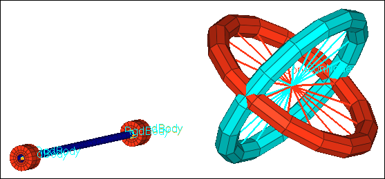
| Note: | A spherical joint consists of two coincident nodes. During analysis, the two coincident nodes are forced to remain coincident, but the bodies attached to each coincident node are allowed to rotate freely about the joint location. |
|
Step 1: Select the LS-DYNA profile and load the Keyword 971 template
| 1. | Start HyperMesh Desktop. |
| 2. | In the User Profile dialog, set the user profile to LsDyna. |
Step 2: Retrieve the file
| 1. | Open a model file by clicking File > Open > Model from the menu bar, or clicking  on the Standard toolbar. on the Standard toolbar. |
| 2. | In the Open Model dialog, open the joints.hm file. The model appears in the graphics area. |
Step 3: Activate coincident node picking
According to the LS-DYNA specification, a joint needs to reference a pair of coincident nodes. The creation of this element requires the selection of coincident nodes. To select coincident nodes, activate the coincident node picking option in HyperMesh, and then select a coincident node. HyperMesh will present you with a selection circle identifying the coincident node ID.
| 1. | Open the Graphics panel by clicking Preferences > Graphics from the menu bar. |
| 2. | Select the coincident picking checkbox. |
Step 4: Change the display
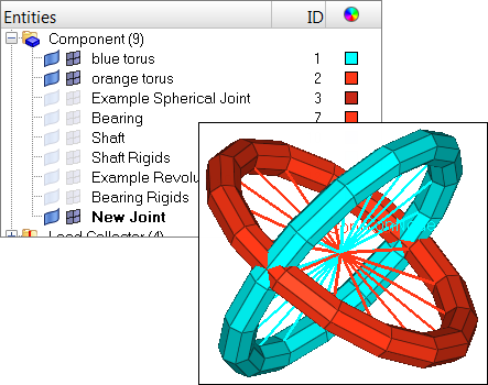
| 1. | In the Model browser, expand the Component folder to display its contents. |
| 2. | Turn off the display of all of the components except for blue torus, orange torus, and New Joint. |
Step 5: Create a spherical joint
Method 1: Create a spherical joint in the Solver browser
| 1. | Open the Solver browser by clicking View > Browsers > HyperMesh > Solver from the menu bar. |
| 2. | In the Solver browser, right-click and select Create > *CONSTRAINED > *CONSTRAINED_JOINT_SPHERICAL > *CONSTRAINED_JOINT_SPHERICAL from the context menu. |
Method 2: Create a spherical joint in the Joints panel
| 1. | Open the Joints panel by clicking Mesh > Create > 1D Elements > Joints from the menu bar. |
| 2. | Set the joint type to spherical. |
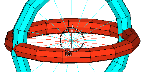
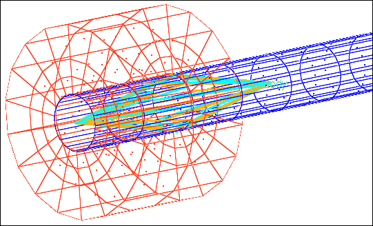
| 3. | Using the node 1 selector, select a node in the center of both tori as indicated in the following image. The coincident node picking mechanism appears and displays two nodes, node 598 and node 1. |
| 4. | While holding down the left mouse button, drag the cursor over the node 598. The blue rigid body attached to this node highlights. |
| 5. | Select node 598 by releasing your left mouse button. HyperMesh activates the node 2 selector. |
| 6. | Using the node 2 selector, select node 1 from the coincident node picking mechanism. |
| 7. | Click create. HyperMesh generates the spherical joint element. |
| Note: | A revolute joint consists of four nodes, two sets of two coincident nodes. During analysis, all four of the revolute joint’s nodes remain at the same location with respect to each other. The bodies attached to the nodes are free to rotate about the axis that lies along the length of the revolute joint. |
Step 6: Change the display
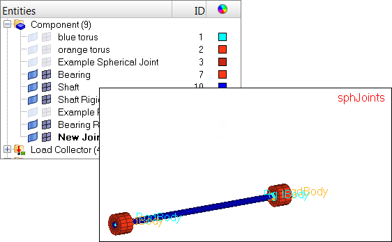
| 1. | In the Model browser, Component folder, turn off the display of all of the components, except Bearing, Shaft, Bearing Rigids, Shaft Rigids, and New Joint. |
Step 7: Create a revolute joint
| 1. | Zoom in on one end of the shaft assembly as indicated in the following image. |
Method 1: Create a revolute joint in the Solver browser
| 1. | In the Solver browser, right-click and select Create > *CONSTRAINED > *CONSTRAINED_JOINT_REVOLUTE > *CONSTRAINED_JOINT_REVOLUTE from the context menu. |
Method 2: Create a revolute joint in the Joints panel
| 1. | From the menu bar, click Mesh > Create > 1D Elements > Joints. |
| 2. | Set the joint type to revolute. |
| 3. | Using the node 1 selector, select a node at the center of one of the rigid link elements as indicated in the following image. The coincident node picking mechanism appears. |
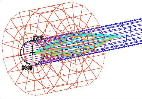
| 4. | Select node 6788, which is attached to the blue rigid link element. |
| Tip: | Drag your cursor over a node in the coincident node picking mechanism to highlight the attached element. |
| 5. | Using the node 2 selector, select a node from the same location as step 7.3. |
| 6. | Select node 6899, which is attached to the orange rigid link element. |
| 7. | Using the node 3 selector, select a node at the center of the opposing pair of blue and orange rigid link elements as indicated in the following image. The coincident node picking mechanism appears. |
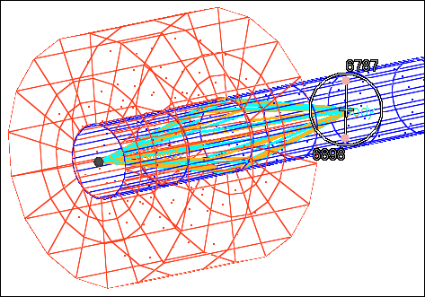
| 8. | Select node 6787, which is attached to the blue rigid link element. |
| 9. | Using the node 4 selector, select a node from the same location as step 7.7. |
| 10. | Select node 6898, which is attached to the orange rigid link element. |
Exercise 2: Checking the Minimum Time Step
The Time subpanel in the check elems panel calculates element time steps, based on the FEA solver, and allows you to check for time steps that fall below a specified value. In explicit codes such as LS-DYNA, it is sufficient that a single element would have a small time step to drastically reduce the total CPU time of the entire job. For this reason the check is used to identify those elements.
Step 1: Retrieve the file
| 1. | Open a model file by clicking File > Open > Model from the menu bar, or clicking on the Standard toolbar. |
| 2. | In the Open Model dialog, open the pene_dyna.hm file. The model appears in the graphics area. |
Step 2: Specify the template
| 1. | Load a solver template by clicking File > Load > Solver Template from the menu bar. |
| 2. | In the Open dialog, navigate to the LS-DYNA folder and open the dyna.key file. |
The time step associated to an element is related to its geometric characteristic and to its material properties such as density and young modulus. For this reason, a material and a valid template need to be associated to the elements. The time step is dependent upon the user profile, so you may want to load a different profile to see how results may change.
Step 3: Check the time steps
| 1. | Open the Check Elements panel by clicking Mesh > Check > Elements > Check Elements from the menu bar. |
| 2. | Go to the time subpanel. |
| 3. | Click check elems. The total number of elements failing the check displays in the Status bar. |

See also
FE Joints panel in the HyperMesh Panels online help.
HyperMesh Tutorials


