Model Files
This exercise uses the floor.hm file, which can be found in the hm.zip file. Copy the file(s) from this directory to your working directory.
Exercise: Recording Shapes
The Record panel gives you the flexibility of making changes to the mesh using panels outside the HyperMorph module and saving them as shapes.
In this exercise you will change a bead using the Node Edit > align node subpanel and record the shape function. You will then reflect the shape to the other side of the mesh to complete the mesh update.
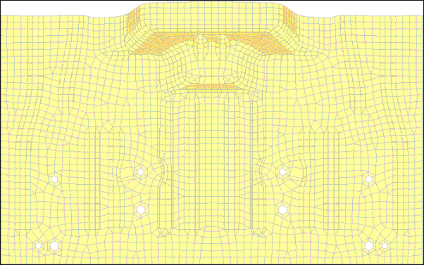
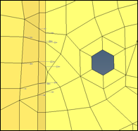
Figure 1: Location to record the nodal movements on and reflect
Step 1: Load and review the model.
Open the HyperMesh file floor.hm.
Step 2: Start recording nodal movements.
| 1. | From the menu bar select Morphing > Free Hand, then select the record subpanel. |
Step 3: Change the bead profile.
| 1. | From the menu bar, select Geometry > Edit >Nodes > Align to enter the align node subpanel. |
| 2. | Select the nodes shown below for the 1st end and 2nd end. |
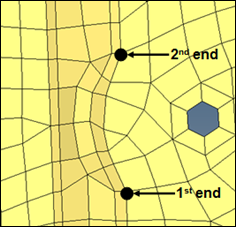
Figure 2: first set of nodes to align
| 3. | Select the nodes between the selected nodes to align the nodes to the 1st end: and 2nd end: nodes. |
| 4. | Repeat the same process to align the next row of nodes (figure 3). |
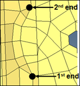
Figure 3: Second set of nodes to align
| 5. | Select the nodes between the selected nodes to align the nodes to the 1st end and 2nd end nodes. |
| 6. | Repeat the same process to align the next row of nodes (figure 4). |
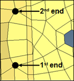
Figure 4: Third set of nodes to align
| 7. | Click return to exit the panel. |
Step 4: Stop the recording.
| 1. | From the menu bar select Morphing > Free Hand, then select the record subpanel. |
This stops the record process.
Step 5: Save the morphed shape.
| 1. | Go to the save shape subpanel. |
| 3. | Toggle save option to as node perturbations. |
| 5. | Click undo all to bring the model to its original position before morphing. |
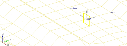
Step 6: Create coordinate system.
| 1. | From the menu bar select Geometry > Create > Systems > Axis Direction. |
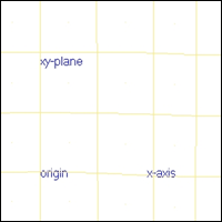
| 2. | For origin select the node with tag origin. |
| • | For x-axis select the node with tag x-axis. |
| • | For xy-plane select the node with xy-plane. |
| 4. | Click return to exit the panel. |
Step 7: Create symmetry.
| 1. | From the menu bar select Morphing > Create > Symmetries. |
| 3. | For symmetry type use 1 plane. |
| 4. | For align with use x-axis. |
| 5. | Select the syst created in step 6. |
Note that 1 plane symmetry is created with a square symbol.
| 7. | Click return to exit the panel. |
Step 8: Reflect shape.
| 1. | From the menu bar select Morphing > Create > Shapes, then select the apply shapes subpanel. |
| 2. | Under shape change the option to reflect shapes. |
| 3. | Under reflect shapes change the option to apply & create. |
| 4. | For shape, select Morph1. |
| 5. | For symmetries, select symm1. |
Summary
The shape (Morph1) is reflected to the other side. Also, the reflected shape has the same name with the suffix 1. The changes that you made on one side are thus transferred to the other side.
See Also:
HyperMesh Tutorials


