Example: Creating and Assigning a Standard Section |

|

|

|

|
|
Example: Creating and Assigning a Standard Section |

|

|

|

|
Example: Creating and Assigning a Standard Section |

|

|

|

|
|
Example: Creating and Assigning a Standard Section |

|

|

|

|
This example illustrates how to create and assign a standard section to an OptiStruct PBARL property. It assumes that the OptiStruct user profile is loaded and the file standard_section.hm from <installation_directory>\tutorials\hm is opened.
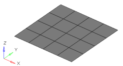
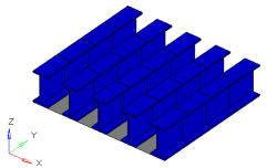
The grey elements in the image to the left represent a structure that needs to be stiffened by adding I-beams down the length of it. The image to the right is the 3D visualization of 1D bar elements running along five separate node paths.
HyperBeam View is the furthest view to the right in the Model browser (![]() ). Standard sections can be created by right-clicking on the browser and selecting the appropriate section. In this case we will be using an OptiStruct I section with the parameters specified below.
). Standard sections can be created by right-clicking on the browser and selecting the appropriate section. In this case we will be using an OptiStruct I section with the parameters specified below.
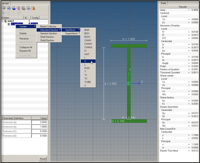
Once HyperBeam solves the cross sectional properties, it is necessary to attach the beam section to a PBAR card image. This can be done in the Property tab of the Create Component dialog in the Model browser.
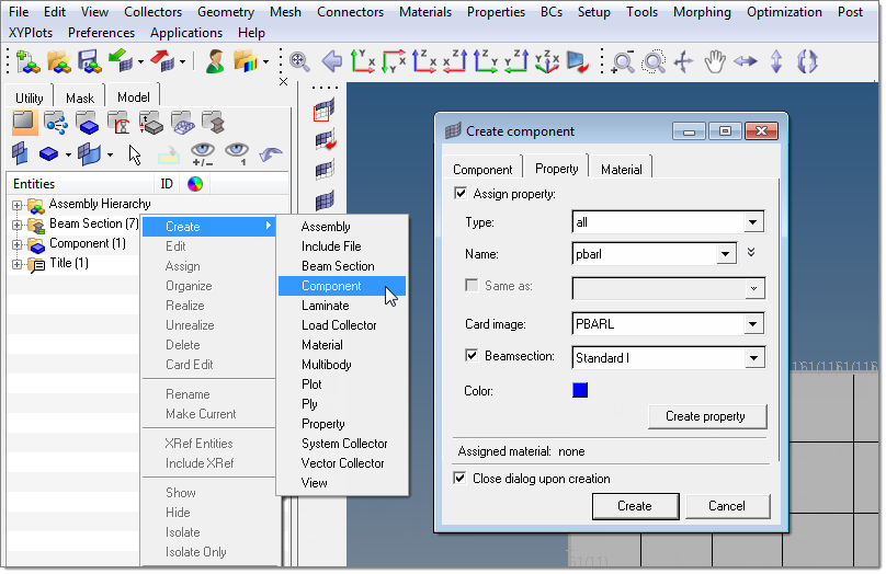
After the new component and property are created with the beamsection attached, the bar element can be defined in the bars panel in the 1D menu-page.
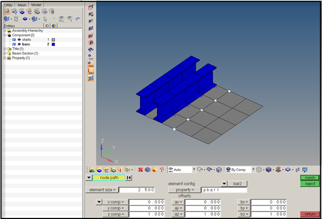
Bar element alignment using HyperBeam sections is very straightforward since standard sections are defined using an absolute y-direction. The direction specified in the Bars panel defines the alignment of the beamsection’s y-direction. In this case, the positive z-direction in the Bars panel will align with the y-direction of the HyperBeam section. Since the centerline of a 1D beam element is defined about the section’s shear center, elemental offsets are frequently required. In this case, we have added z-offsets at both ends of each element to align the I-beams flush with the plate.
To fully visualize the 1D element in HyperMesh, find the display option in the Visualization toolbar (![]() ).
).