Example: Creating and Assigning a Shell Section |

|

|

|

|
|
Example: Creating and Assigning a Shell Section |

|

|

|

|
This example illustrates how HyperBeam can be used to create and assign a shell section to an OptiStruct PBAR property. It assumes that the OptiStruct user profile is loaded and uses the file shell_section.hm from <installation_directory>\tutorials\hm.
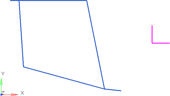
The blue lines are plot elements denoting the beam section. Elements or lines can be used to describe a beam cross section. The purple lines are plot elements used to align the section within HyperBeam.
The shell section subpanel is selected from the hyperbeam panel in the 1D menu-page. The selector type is set to elems and the blue plot elements are selected. Then, select project to plane under cross section plane.

N1, N2, and N3 locations are selected as shown in the following figure. The plane base node, or origin, is set to the shear center.
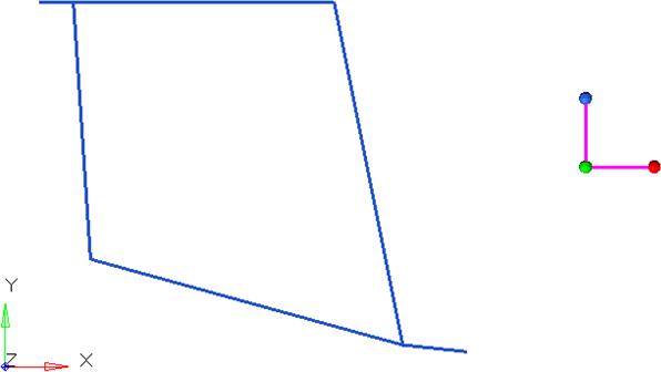
The vector created by N1 to N2 describes the local y-axis used in HyperBeam. N3 describes the positive sense of the z-axis. It is important to note the alignment of the local axes at this point. Later, it will be necessary to know this when the beam section is aligned for bar elements.
HyperBeam View is invoked when you click create.
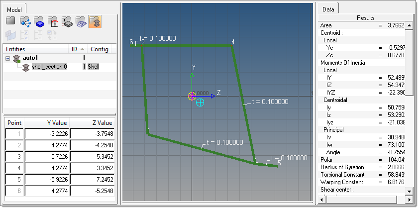
Once selected solves the cross-sectional properties, it is necessary to attach the beam section to a PBAR card image. This can be done in the Property tab of the Create Component dialog in the Model browser.
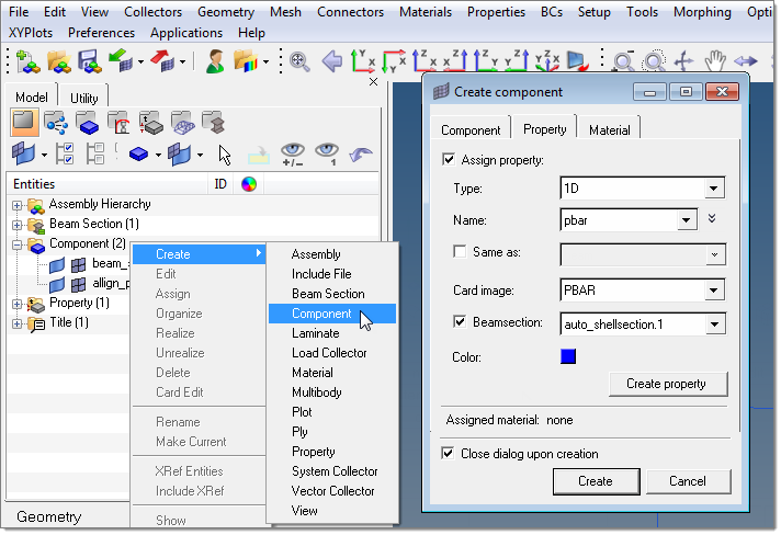
After the new component and property are created with the beamsection attached, the bar element can be defined in the bars panel in the 1D menu-page.
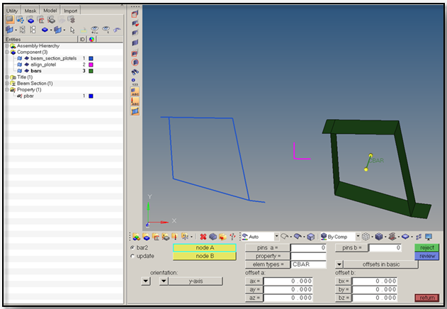
Bar element alignment using HyperBeam sections is very straightforward if the section has been defined using an absolute y-direction. The direction specified in the Bars panel defines the alignment of the beamsection’s y-direction. In this case, the positive y-direction in the Bars panel will align with the y-direction of the HyperBeam section.
To fully visualize the 1D element in HyperMesh, find the display option in the Visualization toolbar (![]() ).
).