Graphics Window |

|

|

|

|
|
Graphics Window |

|

|

|

|
The graphics area displays a representation of the geometric layout of the section. All sections display the following items:
Item |
Description |
|
Local origin of the beamsection |
|
Section Centroid |
|
Shear Center |
|
Element Axis |
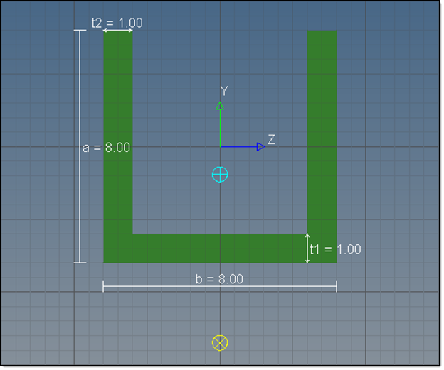
Standard sections display the geometric representation of the section based on the parameter values, which are also listed on the screen.

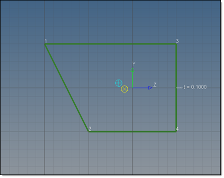
For shell sections each part is drawn with lines connecting the dots that show the section's vertices.

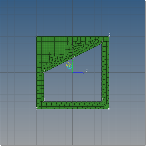
Solid sections can be created and edited using the same tools as a shell section, and the mesh that is used for the section calculations is displayed.

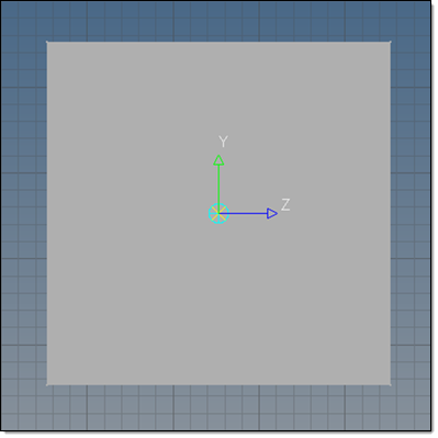
Since generic sections do not inherently have any shape, only a grey box is shown. The centroid and shear center graphics location will update.
