Input
|
Description
|
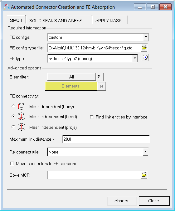
FE configs
|
Type of FE realization (one or more entities) that needs to be converted to connectors. For example, rigid identifies all rigid elements in the model and creates connectors for each one of them. The FE config can be a simple type (weld, rigids, spring, and so on) or custom types defined in the FE config file (ACM, LS-DYNA MAT100, and so on). For custom types, the FE type can be chosen in an additional line.
|
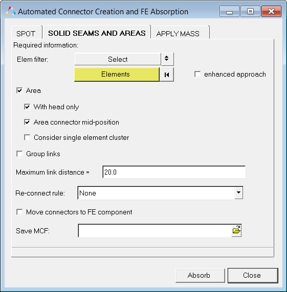
Elem filter
|
Allows you to choose between selecting the displayed elements or a smaller selection from which you can identify and create connectors. The available options are:
|
Checks all elements to find any FE corresponding to the chosen FE config, and converts them to connectors.
|
|
Activates an element collector allowing you to select a portion of the model. In this case, the function searches only the selected elements to find the FE corresponding to the chosen FE config and converts them to connectors.
|
|
Elements
|
Only available when Elem filter is set to select. Allows you to select the elements from which the FE corresponding to the chosen FE config, are determined and converted to connectors.
To clear the elements selector, and de-select all elements, click 
|
FE connectivity
|
Provides information on how the selected FE config is connected to the connecting parts (links). For many FE config types, this option is predetermined. But for some types of weld representations, multiple configurations of connectivity are valid. In such cases, you should select the type that is best for the model. For example, a Nastran CWELD element is a mesh-independent weld, which does not directly connect to the shell elements; depending on how it was generated, plot elements are sometimes used to connect the CWELD to the shells. In such situations, you should select option 2 - mesh independent (head), rather than option 3. Depending on the FE config selected, one or more connectivity types are valid. The three types available are:

|
Mesh dependent
|
Valid for weld elements that share nodal connectivity with the connecting shell parts.
|

|
Mesh independent (head)
|
Valid for weld elements that are mesh-independent (do not share nodal connectivity with the connecting shell parts) but are connected to the shell parts via secondary entities (plot elements, equations, and so on.)
|

|
Mesh independent (projs)
|
Valid for weld elements that are mesh independent (do not share nodal connectivity with the connecting shell parts) and are not connected to the shell parts in any way. Only their projections fall on the shell elements.
|
|
Enable acm pattern recognition
|
When active, particular emphasis is placed on identifying the diameter and the hexa pattern, and connector attributes are appropriately updated.
During the absorption, ACM hexa elements and the attached RBE3 elements are identified. A new connector is created at the center of the hexa elements, and the hexa as well as the RBE3 elements are registered on the green (realized) marked connector.
Only available for various custom ACM realization types.
|
If hexa thickness type is ambigous
|
During absorption of ACM (general), three versions are differentiated (shell gap, equivalence (T1+T2)/2), and constant thickness) and the thickness is determined. Appropriate attributes assigned to the connector, which allows the same rerealization.
Where there is not a clear identifier between shell gap and equivalence(T1+T2)/2, the following options will determine the preference:
| • | Prefer shell gap - Shell gap attributes are preferred when the thickness type is ambiguous. |
| • | Prefer equival(T1+T2)/2 - Equivalence (T1+T2)/2 attributes are preferred when the thickness type is ambiguous. |
Only available for the absorption of the custom ACM (general) realization type.
|
Maximum link distance
|
Only connections in which the link distance is smaller than this value are considered for absorption. Depending on the unit system used, it may be useful to increase or decrease the value. Very large values can affect performance.
|
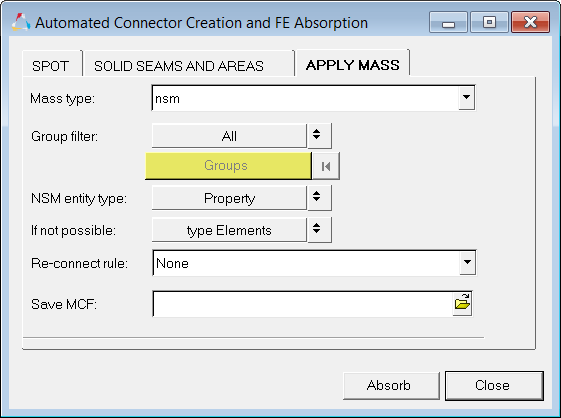
Re-connect rule:
|
Useful in situations where the parts to be connected have been changed/replaced. While realizing the connector, HyperMesh looks for link entities based on the re-connect rule:
|
Use the selected link entity’s IDs to re-connect. If the link entity is not currently in the model, the connector with this re-connect rule will search for entities with the same ID.
|
|
Use the selected link entity’s names to re-connect. If the link entity is not currently in the model, connectors using this re-connect rule search for entities with the same name.
|
|
Move connectors to FE component
|
When active, this option saves the connector entities into the component of the mesh that they are linked to.
|
Save MCF
|
This optional feature allows you to export all the connectors that have been created from FE to a master connection file. Type in a new file name, or click Open and select the file name for the master connection file. If this field is left blank, the master connection file is not created.
|
Absorb
|
Performs the FE absorb process. In this process, all the entities that comprise an FE config are identified. A connector is created at each such location and all the FE entities are added to the realization of the connector.
This process does not (re-)create or renumber any new FE entities; it simply takes the identified group of existing FE that forms a connector and marks it as the realization of the connector. For example, if you choose to absorb all the ACMs in a model, it identifies the hexa elements and the attached RBE3 elements; creates a new connector at the center of the hexa elements; then adds the hexa elements and all the RBE3 elements as the FE realization of the connector (marking the connector as realized/green).
| Note: | The absorbed FE may not be the same as the ones realized by HyperMesh; the absorbed FE behaves similar to the FE created within HyperMesh as part of the connector realization. If you choose to unrealize that connector, or realize it with a new FE type, these absorbed FE are deleted. |
|