In this tutorial, you will learn how to apply a bolted connection to two rear trusses.
Model Files
This exercise uses the frame_assembly_2.hm file, which can be found in the hm.zip file. Copy the file(s) from this directory to your working directory.
Exercise
The Bolt panel creates connectors based on holes within the connected components, using spiders or washers at each end of an RBE connector. When the Bolt panel is active, only bolt-type connectors display in the graphics area; graphics for other connector types are suppressed until you exit the panel. The Bolt panel contains three subpanels:
|
Create and realize bolt connectors in a single process.
|
|
Create, but not realize, bolt connectors.
|
|
Create FE representations of previously-created bolt connectors.
|
Step 1: Retrieve and view the model file.
| 1. | Start HyperMesh Desktop. |
| 2. | In the User Profile dialog, select OptiStruct. |
| 4. | Open a model file by clicking File > Open > Model from the menu bar, or clicking  on the Standard toolbar. on the Standard toolbar. |
| 5. | In the Open Model dialog, open the frame_assembly_2.hm file. A model appears in the graphics area. |
| 6. | Observe the model using various visualization options available in HyperMesh (rotation, zooming, and so on). |
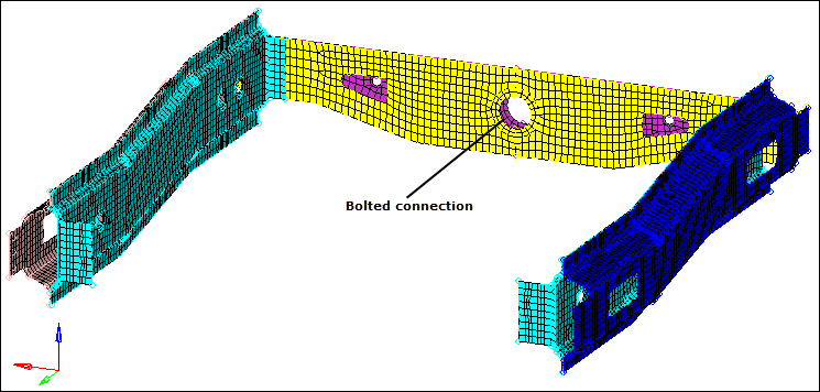
Create a bolted connection between the two rear truss parts.
Step 2: Display only the assembly assem_5 for elements and geometry.
| 1. | In the Model browser, click  (Model View). (Model View). |
| 2. | Expand the Assembly Hierarchy folder and sub-folders. |
| 3. | Set the entity selection to  (Elements and Geometry). (Elements and Geometry). |
| Note: | This options turns on/off both elements and geometry when you perform right-click operations in the Model browser. |
| 4. | Right-click on assem_5 and select Isolate from the context menu. HyperMesh only displays the components that are in the assem_5 assembly. |
| 5. | Right-click on the Con_Rear_Truss component and select Make Current from the context menu. |
Step 3: Load the Connector Browser.
| 1. | Open the Connectors browser by clicking View > Browsers > HyperMesh > Connector from the menu bar. |
| 2. | Review the layout of the Connector browser. Currently there are no components or connectors listed because there are no connectors in the model. |
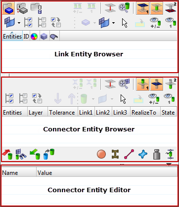
| Note: | You can use the Connector browser to view and manage the connectors in your model. The top portion of the browser is referred to as the Link Entity browser, and it displays information about the linked entities in your model. The middle portion is referred to as the Connector Entity browser, and it contains a list of the connectors in your model. The bottom portion of the browser is referred to as the Connector Entity Editor, and it displays attributes assigned to the connector(s) selected in the Connector Entity browser. HyperMesh groups the connectors based on their connection type. |
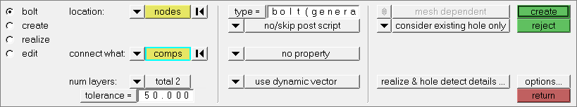
Step 4: Create a bolt connector.
| 1. | Open the Bolt panel by right-clicking in the Connector Entity browser and selecting Create > Bolt from the context menu. |
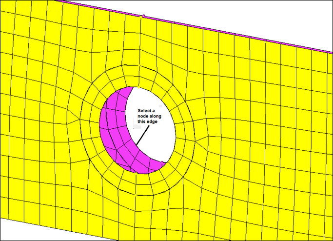
| 2. | Set the location selector to nodes. |
| 3. | Select a node on the edge of the hole in the Rear_Truss_1 component as indicated in the following image. |
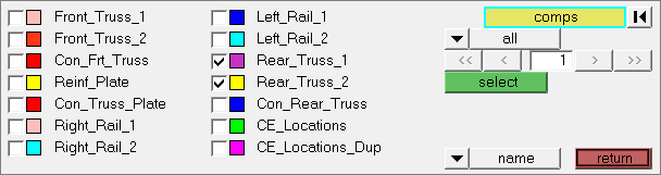
| 4. | Set the connect what selector to comps. |
| 6. | Select the components, Rear_Truss_1 and Rear_Truss_2. |
| 8. | In the tolerance= field, enter 50. |
| Note: | The connector will connect any selected entities within this distance of itself. |
| 9. | Click type= and select bolt (general). |
| Note: | Re-realizing the connector will allow you to see the different bolt types. |
| 10. | Click realize & hole detect details. |
| 11. | In the max dimension = field, enter 60 to ensure that the diameter of the picked hole will be captured. |
| Note: | Ensure the display of the current component is turned on. |
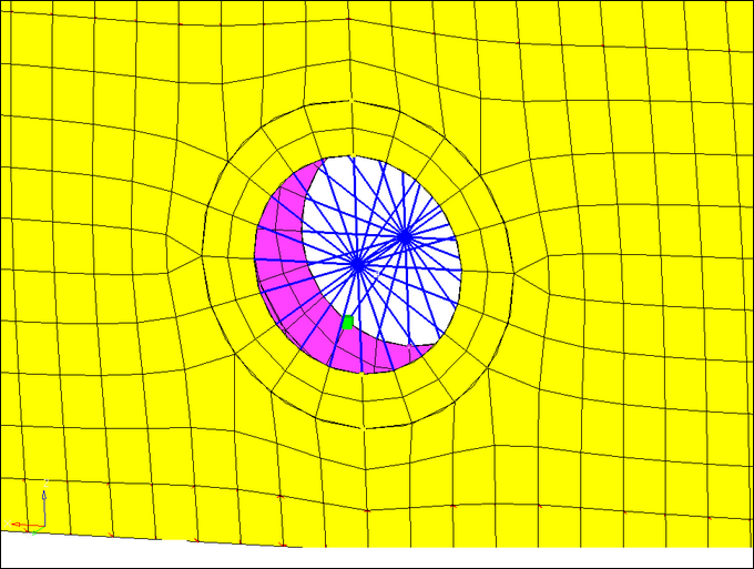
Bolted connection
| 14. | To access the main menu, click return. |
See Also:
HyperMesh Tutorials


