Model Files
This exercise uses the morphing_1.hm file, which can be found in the hm.zip file. Copy the file(s) from this directory to your working directory.
Exercise: Using Domains and Handles
In this exercise you will create domains and handles, and morph the model.
Step 1: Load and review the model.
Open and review the HyperMesh model morphing_1.hm.
Step 2: Auto generate 2-D domains and handles.
| 1. | Click the Morphing menu in the menu bar and select Create > Domains. |
| 2. | Change the create method to auto functions. |
Based on the model’s geometric features, all of the model’s elements are organized into various domains and local handles are created and associated with the domains.
Step 3: Move elements into a new 2-D domain.
| 1. | Set the selector to 2D domains. Toggle to the elems selector if not already there. |
| 2. | Click  to clear the elements that were already selected. to clear the elements that were already selected. |
| 3. | Using elems >> by window, select the elements indicated in figure 1. |
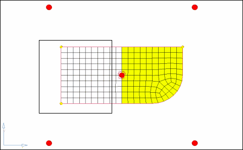
Figure 1: Elements to select to move into a new domain
| 4. | Verify that partition 2D domains is active. |
| 5. | Click create to create the domain. |
Local handles are created for the new domain. You should now have two local domains. Elements can only belong to one domain at a time. Thus, the elements you selected were moved into the new domain. This functionality makes it very easy to group elements into different domains.
Step 4: Split the edge domain of the radius to have more control when morphing.
| 1. | Click the edit edges subpanel in the Morphing > Domains panel. |
| 2. | Verify that the split option is selected. |
| 3. | With the domain selector active, select the edge domain of the part’s radius as indicated in the Figure 2. |
The node selector automatically becomes active once the edge domain is selected. Click the domain selector to make it active and see that you selected the desired edge domain.
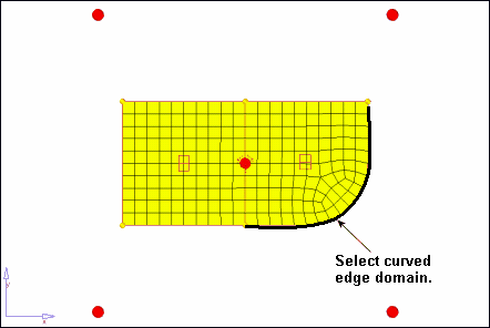
Figure 2: Edge domain to select
| 4. | Click the node selector to make it active. |
| 5. | Select the node on the positive Y-axis end of the radius, as indicated in the image Figure 3. |
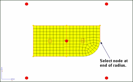
Figure 3: Node selection to split the edge domain of the radius
| 6. | Click split to split the edge domain at the node. |
| 7. | Repeat the above process to further split the edge domain of the radius, this time at the node indicated in the Figure 4. |
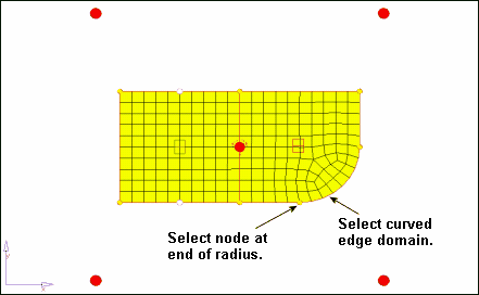
Figure 4: Node selection to further split the edge domain of the radius
| 8. | When complete, click return to exit the panel. |
Step 5: Add local handles to the 2-D domain on the part’s left side.
| 1. | Click the Morphing menu, and pick Create > Handles. |
| 2. | For name=, enter local. |
| 3. | Click the attached to: domain selector to make it active. |
| 4. | Select the 2-D domain on the part’s left side by selecting its red icon, as indicated in the following image. |
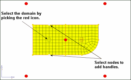
Figure 5: Adding handles to a 2-D domain
| 5. | Click the by nodes: nodes selector to make it active. |
| 6. | Select the two nodes as indicated in the previous image. |
| 7. | Click create to create the handles and add them to the 2-D domain. |
| 8. | Click return to exit the panel. |
Step 6: Perform basic morphing to understand how domains and handles interact with each other and the mesh.
| 1. | Click the Morphing menu, and select Morph. |
| 2. | Select the move handles subpanel if not already there. |
| 3. | Change the mode to interactive if not already set. |
| 4. | With the handles selector active, select the two handles on the right-hand end of the part, as indicated in figure 6. |
If you select one or more handle, those handles follow the handle you drag (in Step 6.10, following).
| 5. | Switch from manipulator to on plane. |
| 6. | Click the N1 selector to make it active. |
| 7. | For N1, N2, and N3, select any three nodes on the model to define a plane. |
The message, “pick handles and move to new location” appears in the status bar.
| 9. | Click on and drag one of the selected handles to morph the part. |
As you drag the handle, the mesh’s size and shape is adjusted. Notice that the following occurs as the selected local handle is moved:
| • | The handles selected in step 6.2 above follow the handle you are dragging. |
| • | All of the elements belonging to the selected local handle’s 2-D domain are affected by moving that local handle. |
| • | The 2-D domain’s non-selected local handles act like anchors (they do not move). |
| • | The nodes on the edge domains and between any two non-selected local domains do not move. |
| • | None of the elements in the other 2-D domain are affected. |
| 10. | Release the mouse button to complete the morphing operation. |
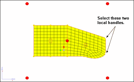
Figure 6: Example result of morphing the model
The HyperMorph module allows for multiple levels of undo and redo for all morphing operations. This functionality is available for any particular HyperMesh session and its current model as long as the session and its model remain open.
| 12. | Click to clear the selected handles. |
| 13. | With the handles selector active, select one or more global handles. |
| 15. | Click on and drag any global handle to morph the part. |
Summary
The following occurs as the selected global handle is moved:
| • | The handles selected in Step 6.2 above follow the handle you are dragging. |
| • | The non-selected global handles act like anchors (they do not move). |
| • | All of the elements, local handles and edge domains are affected. |
See Also:
HyperMesh Tutorials


