In this tutorial, you will learn how to:
| • | Mesh the part to determine poor element quality |
| • | Remove interior fixed points |
| • | Replace closely placed fixed points |
Topological details of the geometry may affect the quality of the mesh created from the surfaces. Some of these details may not reflect any major feature of the part’s shape, and can be removed without concern. When modifying the topology affects the shape of the surfaces, a compromise must be made between the part shape and the element quality necessary for the analysis. Other times, adding topological features that do not change the shape of the part may actually help create a better quality mesh.
Model Files
This exercise uses the clip_refine.hm file, which can be found in the hm.zip file. Copy the file(s) from this directory to your working directory.
Exercise: Refining Topology to Achieve a Quality Mesh
Step 1: Open the model file, clip_refine.hm.
| 1. | From the menu bar, click File > Open > Model. |
| 2. | In the Open Model dialog, open the clip_refine.hm model file. |
| 3. | Take a few moments to observe the model using the different visual options available in HyperMesh (rotation, zooming, etc.). |
Step 2: Create a preliminary mesh.
| 1. | To open the Automesh panel, click Mesh > Create > 2D AutoMesh from the menu bar, or press F12. |
| 2. | Set the entity selector to surfs. |
| 3. | Go to the size and bias subpanel. |
| 4. | In the element size = field, type 2.5. |
| 5. | From the mesh type list, select mixed. |
| 6. | Switch the meshing mode from interactive to automatic. |
| 7. | Click surfs >> displayed. |
| 8. | Click mesh. HyperMesh meshes the surfaces. |
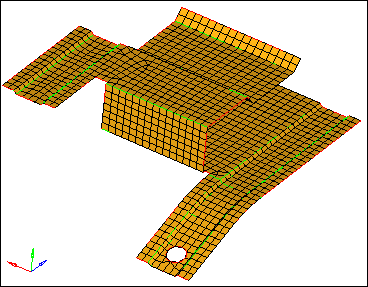
Initial mesh on the defeatured clip model
Step 3: Review the mesh quality.
| 1. | Take a minute to rotate, zoom, and pan the model to review the mesh that was created. Pay attention to the locations where the mesh was not created in rows and columns of quads. |
| 2. | To open the Check Elements panel, click Mesh > Check > Elements > Check Elements from the menu bar, or press F10. |
| 3. | Go to the 2-d subpanel. |
| 4. | In the length < field, enter 1. |
| 5. | To evaluate the minimum length, click length. HyperMesh highlights the elements that failed the check. |
| 6. | To exit the panel, click return. |
| 7. | In the Model browser, Component folder, click  next to Middle Surface to turn off the display of it's elements. next to Middle Surface to turn off the display of it's elements. |
Step 4: Remove short edges by combining fixed points.
| 1. | To open the Replace panel, click Geometry > Edit > Fixed Points > Replace from the menu bar. |
| 2. | Verify that the moved points selector is active. |
| 3. | Select the lower fixed point as indicated in the following image. |
| Tip: | If there are no visible fixed points on your model, verify that  is selected on the Display toolbar. is selected on the Display toolbar. |
| 4. | Activate the retained point selector. |
| 5. | Select the upper fixed point as indicated in the following image. |
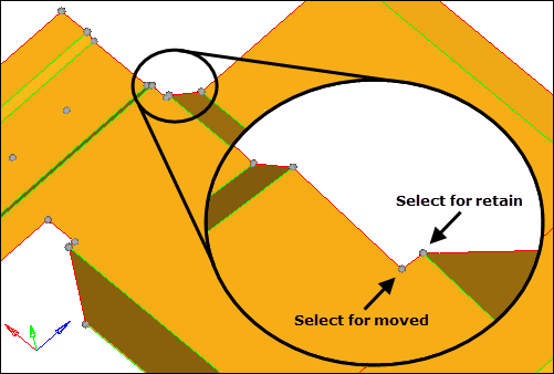
Selecting fixed points to be combined
Step 5: Remove the fixed points interior to all surfaces.
You should still be in the Points panel.
| 1. | Go to the suppress subpanel |
| 2. | Under at cursor, verify that the point selector is active. |
| 3. | Select the four fixed points as illustrated in the following image. HyperMesh deletes each fixed point when you select it. |
These fixed points are left over from a defeaturing operation where small holes (pinholes) were removed. They could remain without greatly sacrificing the element quality, given the element size used for the mesh, but the mesh would be better without them.
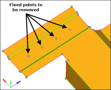
Fixed points to be removed
| 4. | To exit the panel, click return. |
Step 6: Add edges to the surfaces to control the mesh pattern.
| 1. | To open the Trim with Nodes panel, click Geometry > Edit > Surfaces > Trim with Nodes from the menu bar. |
| 2. | Under node normal to edge, click node. |
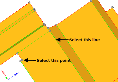
| 3. | Zoom into the area illustrated in the following image and select the indicated fixed point. |
| 4. | With the lines selector now active, select the line shown in the image below. HyperMesh creates an edge from the location of the fixed point perpendicular to the line. |
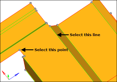
Select fixed point and line to split the surface.
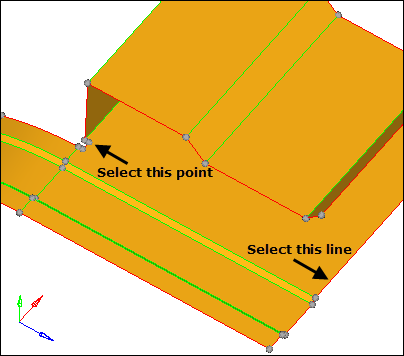
| 5. | Repeat steps 6.2 through 6.4 for the point and line illustrated in the following image. |
Select fixed point and line to split the surface.
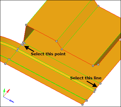
| 6. | Repeat steps 6.2 through 6.4 for the point and line illustrated in the following image. |
Select fixed point and line to split the surface.
| 7. | Repeat steps 6.2 through 6.4 for the point and line illustrated in the following image. |
Select fixed point and line to split the surface
Step 7: Add edges to the surfaces to control the mesh pattern.
| 1. | Go to the trim with surfs/planes subpanel. |
| 2. | In the with plane column, verify that the surfs selector is active. |
| 3. | Select the five surfaces indicated in the following image. |
Surfaces to be selected for splitting
| 4. | Verify that the direction selector is set to N1, N2, N3. |
| 5. | Click N1 to make the selector active. |
| 6. | Press and hold your left mouse button, move it over the edge as indicated in the following figure, and then release it when the cursor changes to a square with a dot in the center  . . |
| 7. | Click two points anywhere along the edge. Do not click a third. Hypermesh places nodes on the line for N1 and N2. |
| 8. | To open the Distance panel, press F4. |
| 9. | Go to the three nodes subpanel. |
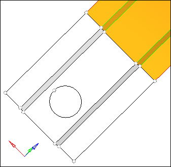
| 10. | Press and hold your left mouse button, move it over the edge of the hole as indicated in the following image, and then release it when the cursor changes to a square with a dot in the center . |
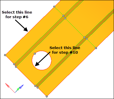
Select fixed point and line to split the surface
| 11. | Click three points anywhere along the edge. HyperMesh places temporary nodes on the line representing N1, N2, and N3. |
| Note: | The technique you used to create nodes to select where none existed before can be used in any place where nodes need to be selected but do not exist in the model. You can create nodes in this manner on lines, surfaces and elements. For more details, see the HyperMesh online help. Pick the index and type, Picking Nodes on Geometry or Elements. |
| 12. | Click circle center. HyperMesh creates a node at the center of the hold. |
| 13. | To exit the Surface Edit panel, click return. |
| 14. | Activate the B selector. |
| 15. | Select the node that was just created at the center of the hole. |
| 16. | Click trim. HyperMesh trims the surfaces through the center of the hole. |
| 17. | To exit the panel, click return. |
Step 8: Suppress shared edges causing a small edge.
| 1. | To go to the (Un)suppress panel, click Geometry > Edit > Surface Edges > (Un)Suppress from the menu bar. |
| 2. | Select the five lines illustrated in the following image. |
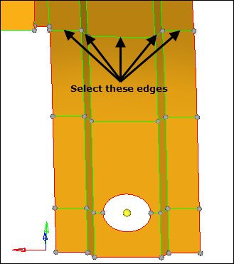
Surface edges to suppress by toggling
| 3. | Click suppress. HyperMesh suppresses each line, which in indicated by a blue, dashed line. |
Step 9: Remesh the part.
In this step, you will remesh the surfaces of the part, using the automatic mode, a size of 2.5, and the mixed mesh type.
| 1. | In the Model browser, Component folder, click next to Middle Surface to display it's elements. |
| 2. | To open the Automesh panel, click Mesh > Create > 2D AutoMesh from the menu bar, or press F12. |
| 3. | Verify that elem size = is set to 2.5 and the mesh type is set to mixed. |
| 4. | To select all of the displayed surfaces, click surfs >> displayed. |
Step 10: Review the mesh quality.
| 1. | Take a minute to rotate, zoom, and pan the model to review the mesh that was created. The mesh consists completely of rows and columns of quads. |
| 2. | To open the Check Elements panel, click Mesh > Check > Elements > Check Elements from the menu bar, or press F10. |
| 3. | Go to the 2-d subpanel. |
| 4. | In the length < field, enter 1. |
| 5. | To evaluate the minimum length, click length. HyperMesh highlights only two elements that failed the check. Both of these elements failed the check because of the shape of the part. These elements are not too small compared to the global element size, therefore you can leave them as is. |
| 6. | To open the Automesh panel, click Mesh > Create > 2D AutoMesh from the menu bar, or press F12. |
| 7. | Go to the QI optimize subpanel. |
| 8. | Verify that elem size = is set to 2.5 and the mesh type is set to mixed. |
| 10. | In the Criteria File Editor dialog, enter 2.500 in the Target element size field. |
| 13. | To select all of the displayed surfaces, select surfs >> displayed. |
| 14. | Click mesh. HyperMesh replaces the old mesh with a new mesh. |
| 15. | If there is a message saying, "There is a conflict between the user requested element size and quality criteria ideal element size," click the Recompute quality criteria button using a size of 2.5. |
| 16. | To access the Quality Index panel, click Mesh > Check > Elements > Quality Index from the menu bar. |
| 18. | Verify that the comp. QI is 0.01. This low value indicates that the mesh is good quality. The higher the number, the lower the mesh quality. |
Step 11 (Optional): Save your work.
The part is now meshed and ready to be set up for an analysis. Save the model, if desired.
| 1. | From the menu bar, click File > Save > Model. |
See Also:
HyperMesh Tutorials


