In this tutorial, you will learn what solid geometry and topology is, and what 3D topology looks like.
Solids are geometric entities that define a three-dimensional volume. Geometric entities are defined as follows:
| • | Point: 0 dimensional; has only x, y, and z coordinates |
| • | Line: one-dimensional; has length, can be curved through three-dimensional space |
| • | Surface: two-dimensional; has an area |
| • | Solid: three-dimensional; has a volume |
The use of solid geometry is helpful when dividing a part into multiple volumes, for example, to divide a part into simple, mappable regions for hex meshing.
Model Files
This exercise uses the solid_geom.hm file, which can be found in the hm.zip file. Copy the file(s) from this directory to your working directory.
Exercise: Creating and editing solid geometry
Step 1: Retrieve model file, solid_geom.hm.
| 1. | Start HyperMesh Desktop. |
| 2. | From the menu bar, click File > Open > Model. |
| 3. | In the Open Model dialog, open the solid_geom.hm model file. |
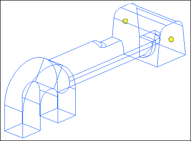
Step 2: Create solid geometry from the bounding surfaces.
| 1. | To open the Bounding Surfaces, click Geometry > Create > Solids > Bounding Surfaces from the menu bar. |
| 2. | Verify that the Auto select solid surfaces check box is selected. |
| 3. | Select one surface on the part. HyperMesh automatically selects all of the surfaces. |
| 4. | Click create. HyperMesh creates the solid, and the status bar displays message that says one solid has been created. |
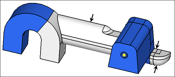
| Note: | The solids are identified by thicker lines than surfaces. |
| 5. | To exit the panel, click return. |
Step 3: Create a solid geometry cylinder using primitives.
| 1. | To open the Cylinder Full panel, click Geometry > Create > Solids > Cylinder Full from the menu bar. |
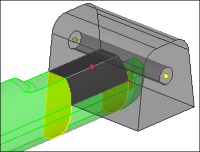
| 2. | Click bottom center and then select one of the temporary nodes as illustrated in the following image. The cursor advances to the normal vector selector. |
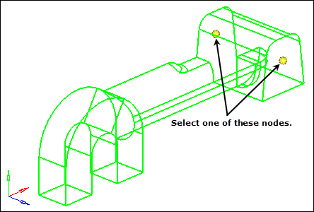
| 3. | Select the remaining temporary node shown in the previous image. |
| 4. | In the Base radius=, enter 1.5. |
| 5. | In the Height= field, enter 25. |
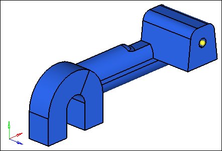
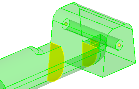
| 6. | Click create. HyperMesh creates solid cylinder in the middle of the first solid that was created. |
| 7. | To exit the panel, click return. |
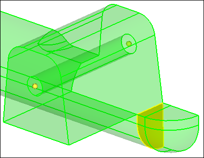
Step 4: Subtract the cylinder’s volume from the rest of the part.
| 1. | To open the Boolean subpanel, click Geometry > Edit > Solids > Boolean from the menu bar. |
| 2. | Verify that operation type: is set to simple (combine all). |
| 3. | Set operation: to A-B (remove B from A). |
| 4. | Verify that the A: solids selector is active, and then select the original solid. |
| 5. | Activate the B: solids selector, and then select the solid cylinder created in step 3. |
| 8. | To confirm the material has been removed, click  on the Visualization toolbar and rotate the model to inspect the part. on the Visualization toolbar and rotate the model to inspect the part. |
Step 5: Split the solid geometry using bounding lines.
| 1. | To go to the trim with lines subpanel, click Geometry > Edit > Solids > Trim with Lines subpanel. |
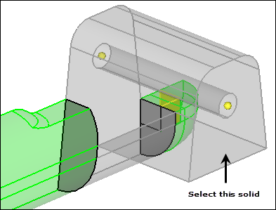
| 2. | Activate the with bounding lines selector and set it to solids. |
| 3. | Click anywhere on the model to select it. |
| 4. | Under the with bounding lines selector, activate the lines selector. |
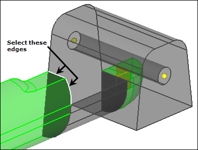
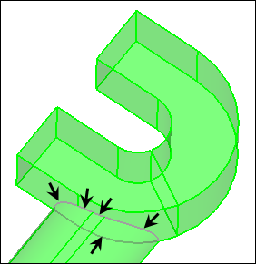
| 5. | Select the four lines indicated in the following image. |
| 6. | Click trim. HyperMesh trims a plane. |
| Note: | The two solids now intersect. |
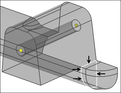
Step 6: Split the solid geometry using a cut line.
In this step, you should still be in the Solid Edit panel, trim with lines subpanel.
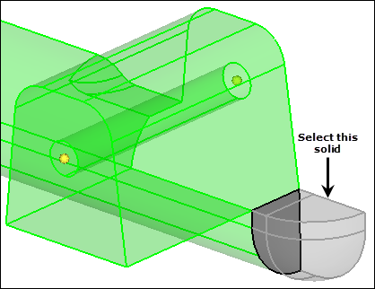
| 1. | Activate the with cut lines selector and set it to solids. |
| 2. | Select the small, tetrahedral shaped solid created in step 5. |
| 3. | In the Model browser, View folder, right-click on View1 and select Show from the context menu. |
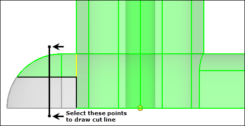
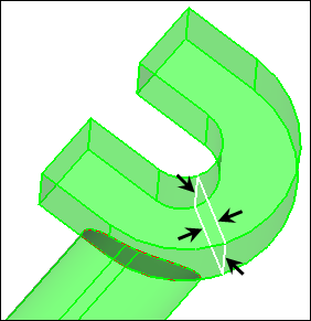
| 5. | To define the end points of a line that roughly divides the tetrahedral solid in half, select the two locations indicated in the following image. |
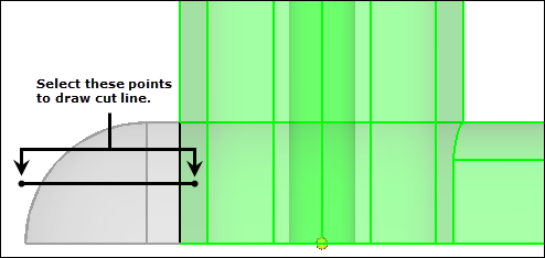
| 6. | To split the solid, middle-mouse click. |
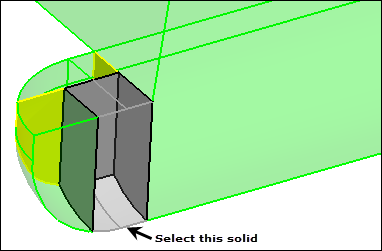
| 7. | Select the half of the original tetrahedral solid indicated in the following image. |
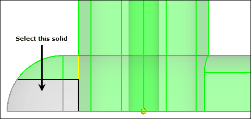
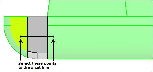
| 8. | To split the solid indicated in the following image, repeat steps 6.4 through 6.6. |
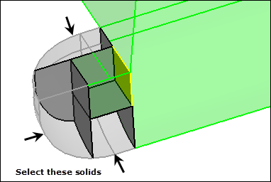
| 9. | Select the solid indicated in the following image. |
| 10. | In the Model browser, View folder, right-click on View2 and select Show from the context menu. |
| 11. | To split the solid indicated in the following image, repeat steps 6.4 through 6.6. |
Step 7: Merge solids together.
In this step, you should still be in the Solid Edit panel.
| 1. | Go to the merge subpanel. |
| 2. | Activate the to be merged: solids selector. |
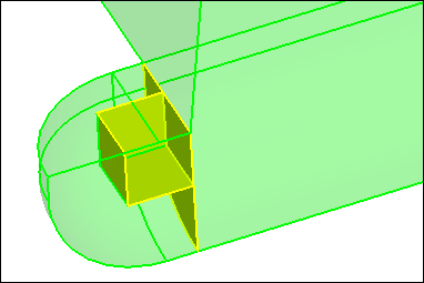
| 3. | Select the three solids indicated in the following image. |
| 4. | Click merge. HyperMesh merges the solids. |
| Note: | The resulting solids in the tetrahedral area should resemble the following image. There should be two solid entities, with one of them being hexahedral in shape in the corner. |
Step 8: Split the solid geometry with a user-defined plane.
In this step, you should still be in the Solid Edit panel.
| 1. | Go to the trim with plane/surf subpanel. |
| 2. | From the Model browser, View folder, right-click on View3 and select Show from the context menu. |
| 3. | Activate the with plane selector and set to solids. |
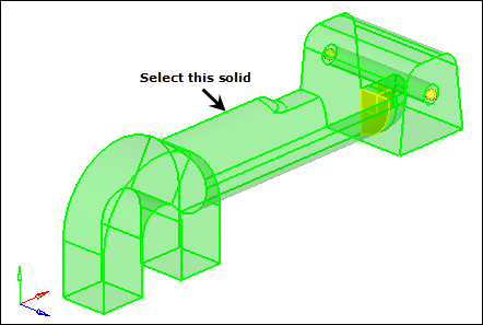
| 4. | Select the large solid representing the majority of the part. |
| 5. | Set the orientation vector to N1, N2, N3. |
| 6. | With N1 active, press and hold your left mouse button, and move the mouse cursor over one of the edges indicated in the following image. HyperMesh highlights the edge. |
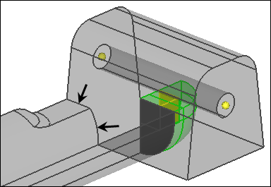
| 7. | Release the mouse button, and left-click in the middle of the edge. A green temp node appears at the location to indicate the selection for N1. |
| Note: | The plane selector advances to the N2 selection. |
| 8. | In the same manner, highlight the other line shown in the previous image. |
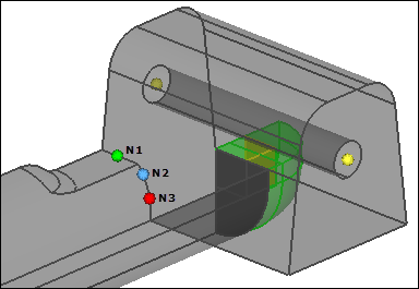
| 9. | Release the mouse button, and select two nodes along its length. |
| Note: | Your selection should look similar to the following image. |
| 10. | Click trim. HyperMesh trims the solid. |
Step 9: Split the solid geometry with a swept line.
In this step, you should still be in the Solid Edit panel.
| 1. | Go to the trim with lines subpanel. |
| 2. | Activate the with sweep lines selector and set it to solids. |
| 3. | Select the solid with the cylinder removed. |
| 4. | Activate the lines selector. |
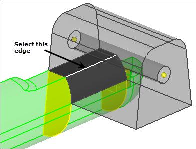
| 5. | Select the edges indicated in the following image. |
| 6. | Under sweep to:, set the orientation vector to x-axis. |
| 7. | Under the orientation vector, verify that sweep all is selected. |
| 6. | Click trim. HyperMesh trims the solid. |
Step 10: Split the solid geometry with a principal plane.
In this step, you should still be in the Solid Edit panel.
| 1. | Go to the trim with plane/surf subpanel. |
| 2. | Activate the with plane selector and set it to solids. |
| 3. | Select the solid with the cylinder removed. |
| 4. | Set the orientation vector to z-axis. |
| 5. | Press and hold your left mouse button, and move the mouse cursor over the edge indicated in the following image. HyperMesh highlights the edge. |
| 6. | Release the mouse button, and left-click anywhere along the edge. A purple temp node appears at the location to indicate the selection for the base node. |
| 7. | Click trim. HyperMesh trims the solid. |
| 8. | To exit the panel, click return. |
Step 11: Split the solid geometry by creating surfaces inside the solids.
| 1. | To open the Spline/Filler subpanel, click Geometry > Create > Surfaces > Spline/Filler from the menu bar. |
| 2. | Clear the Auto create (free edges only) and keep tangency check boxes. |
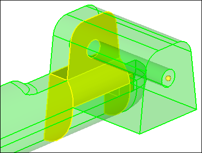
| 3. | Select the five lines indicated in the following image. |
| 4. | Click create. HyperMesh creates a surface. |
| 5. | To exit the panel, click return. |
| 6. | To go to the Trim with Plane/Surface subpanel, click Geometry > Edit > Solids > Trim with Plane/Surfaces from the menu bar. |
| 7. | Activate the with surfs selector and set to solids. |
| 8. | Select the solid with the cylinder removed. |
| 9. | Activate the surfs selector. |
| 10. | Select the surface that you created in step 11.4. |
| 12. | To exit the panel, click return. |
| 13. | Go to the Spline/Filler subpanel. |
| 14. | Set the entity selector to lines. |
| 15. | Select the four lines indicated in the following image. |
| 16. | Click create. HyperMesh creates a surface. |
| 17. | To exit the panel, click return. |
| 18. | Go to the Trim with Plane/Surface subpanel. |
| 19. | Activate the with surfs selector and set it to solids. |
| 20. | Select the solid you created a surface for in step 11.16. |
| 21. | Activate the surfs selector. |
| 22. | Select the surface that you created in step 11.16. |
| 23. | Clear the extend trimmer check box. |
| 25. | To exit the panel, click return. |
Step 12: Suppress extraneous edges on the part.
| 1. | To open the (Un)Suppress subpanel, click Geometry > Edit > Surface Edge > (Un)Suppress from the menu bar. |
| 2. | Click lines >> by geoms. |
| 3. | Verify that the solids selector is active. |
| 4. | Select the three solids indicated in the following image. |
| Tip: | To view a more efficient graphical representation of the solids, set the surface display mode to  . . |
| 5. | Click add to selection. |
| 6. | In the breakangle = field, enter 45. |
| 7. | Click suppress. HyperMesh suppresses the edges. |
| 8. | To exit the panel, click return. |
See Also:
HyperMesh Tutorials


