In this tutorial, you will learn how to:
| • | Load the ANSYS user profile |
| • | Retrieve the HyperMesh model files for this tutorial |
| • | Apply the real constants for the elements of the model |
| • | Apply the material properties for elements of the model |
| • | Update each component with respective element type |
| • | Update each component with respective real constants |
| • | Update each component with respective material properties |
The model setup includes: setting up of element type, real constants, material properties and component structure in HyperMesh for ANSYS.
Model Files
This exercise uses the chapter2_1.hm and chapter2_2.hm files, which can be found in <hm.zip>/interfaces/ansys/. Copy the file(s) from this directory to your working directory.
Exercise 1
Step 1: Load the ANSYS user profile
| 1. | Start HyperMesh Desktop. |
| 2. | In the User Profile dialog, select Ansys. |
Step 2: Retrieve the model file
| 1. | Open a model file by clicking File > Open > Model from the menu bar, or clicking  on the Standard toolbar. on the Standard toolbar. |
| 2. | In the Open Model dialog, open the chapter2_1.hm file. |
| 3. | If your model's elements and mesh lines are not shaded, click  on the Visualization toolbar. on the Visualization toolbar. |
Step 3: Add an element type
| 1. | In the Model browser, right-click and select Create > Sensor from the context menu. HyperMesh creates and opens a sensor (Et Type) in the Entity Editor. |
| Note: | The Entity Editor displays the new Sensor's (Et Type) card details. |
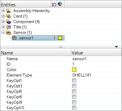
| 2. | For Name, enter a new name for the Et Type. |
| 3. | Optional: For ID, enter a new ID for the Et Type. |
| Note: | By default, HyperMesh sets the ID to 1. If you create a new Et Type, HyperMesh will set the ID to n+1. |
| 4. | For Element Type, select a new element type. |
| Note: | By default, HyperMesh set the Element Type to SHELL181. The elements in this model are of type SHELL181, therefore you do not need to change the element type for this tutorial. |
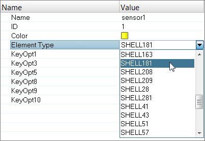
SHELL181
| • | Suitable for analyzing thin to moderately-thick shell structures. It is a 4-node element with six degrees of freedom at each node: translations in the x, y, and z direction; rotations about the x, y, and z axes (if the membrane option is used, the element has translational degrees of freedom only). The degenerate triangular option should only be used as filler elements in mesh generation. |
| • | Well-suited for linear, large rotation, and/or large strain nonlinear applications. Change in shell thickness is accounted for nonlinear analysis. In the element domain, both full and reduced integration schemes are supported. SHELL181 accounts for follower (load stiffness) effects of distributed pressures. |
| • | May be used for layered applications for modeling laminated composite shells or sandwich construction. The accuracy in modeling composite shells is governed by the first order shear deformation theory. |
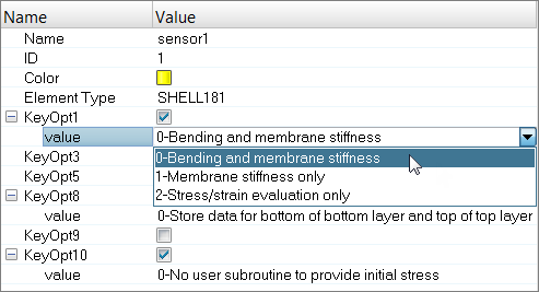
| 5. | Set the element stiffness (KeyOpt1), integration (KeyOpt3), layer data storage (KeyOpt8), thickness (KeyOpt9), and/or initial stress (KeyOpt10) options by selecting their corresponding checkboxes in the Value column. A value appears below each KeyOpt you selected. |
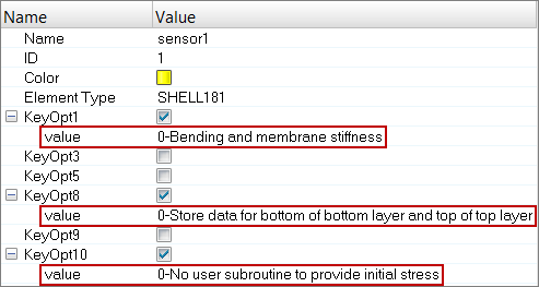
| 6. | For each KeyOpt you selected, assign a value. |
| Note: | For this tutorial, use the default value assigned to each KeyOpt. |
| 7. | Open the Solver browser by clicking View > Browsers > HyperMesh > Solver from the menu bar. |
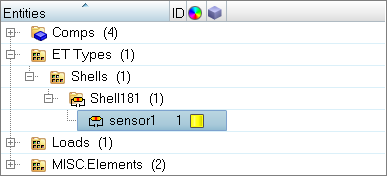
| 8. | Review the ET Type you just created. |
Step 4: Define material properties
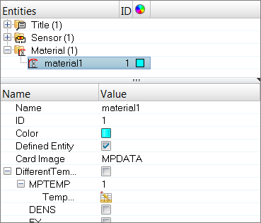
| 1. | In the Model browser, right-click and select Create > Material from the context menu. HyperMesh creates and opens a material in the Entity Editor. |
| 3. | Optional: For ID, enter a new ID. |
| Note: | By default, HyperMesh sets the ID to 1. If you create a new material, HyperMesh will set the ID to n+1. |
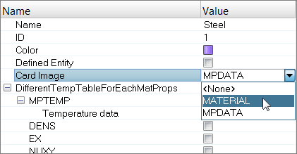
| 4. | Click the Color icon, and select a color. |
| 5. | Set Card Image to MATERIAL. |
| 6. | Select the EX (Elastic moduli) checkbox. |
| 7. | For MP_EX_LEN (Number of Elastic moduli to input), enter 1. |
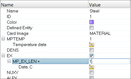
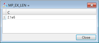
| 8. | Under MP_EX_LEN=, next to Data: C, click  . . |
| 9. | In the MP_EX_LEN= dialog, enter 2.1e5. |
| 11. | Select the NUXY (Minor Poisson's ratio) checkbox. |
| 12. | For MP_NUXY_LEN (Number of Minor Poisson's ratio to input), enter 1. |
| 13. | Under MP_NUXY_LEN=, next to Data: C, click . |
| 14. | In the MP_NUXY_LEN= dialog, enter 0.3. |
| 16. | Go to the Solver browser and review the material you just created. |
Step 5: Create the section card for the shell elements in the model
| 1. | In the Model browser, right-click and select Create > Property from the context menu. HyperMesh creates and opens a property in the Entity Editor. |
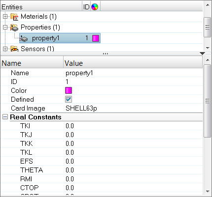
| 3. | Optional: For ID, enter a new ID. |
Ansys sections are supported under property, with a separate ID pool. Sections are created by setting the card image to SECTYPE. All cards created with the SECTYPE card image are organized under one ID pool. Properties created with a card image other than SECTYPE are organized under another ID pool. If you want to use the same IDs in these two pools, enable the allow duplicate IDs option in Preferences > Meshing Options. In earlier versions of HyperMesh (14.0 or before), Ansys sections were supported under beam section collectors.
| Note: | By default, HyperMesh sets the ID to 1. If you create another new beam section collector, HyperMesh will set the ID to n+1. |
| 4. | Click the Color icon, and select a new color. |
| 5. | Set Card Image to SECTYPE. |
| 7. | Under SECDATA, for PLIES, enter 1. |
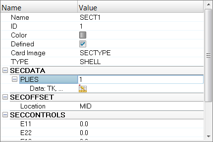
| 8. | Under PLIES, next to Data: TK, click . |
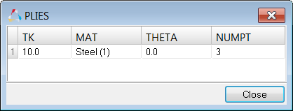
| 9. | In the Plies dialog, enter 10 for TK (ply thickness). |
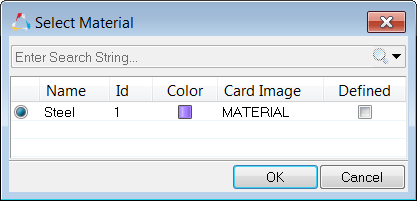
| 10. | For MAT, click Unspecified >> Material. |
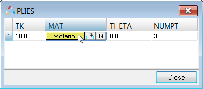
| 11. | In the Select Material dialog, select Steel and then click OK. |
| 12. | For THETA (ply angle), keep the default value 0.0. |
| 13. | For NUMPT (Integration points through ply thickness), enter 3.0. |
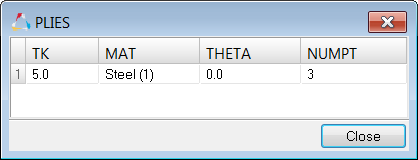
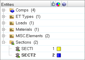
| 15. | In the Model browser, Property folder, right-click on SECT1 and select Duplicate from the context menu. HyperMesh creates a new property using the same card data as SECT1, except a different Name and ID are specified. |
| 16. | For Name, enter SECT2. |
| 17. | Click the Color icon, and select a new color. |
| 18. | Under PLIES, next to Data: TK, click . |
| 19. | In the PLIES dialog, change the value for TK from 10 to 5. |
| 20. | Leave MAT, THETA, and NUMPT unchanged. |
| 22. | Go to the Solver browser and review the two sections you just created. |
Step 6: Update each component with the respective element type, property, material, and section information
| 1. | In the Model browser, Component folder, click Base. The Entity Editor opens and displays the component's corresponding data. |
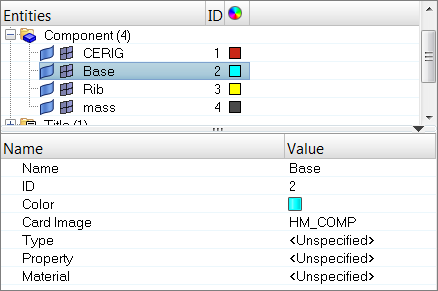
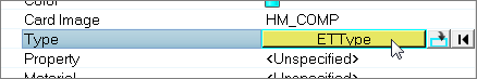
| 2. | For Type, click Unspecified >> ETType. |
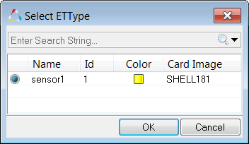
| 3. | In the Select ETType dialog, select sensor1 (SHELL181) and then click OK. |
| 4. | For Property, click Unspecified >> Property. |
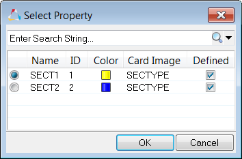
| 5. | In the Select Property dialog, select SECT1 and then click OK. |
| Note: | You do not have to assign a Property or Material to this component, because this information is already defined in SECT1. |
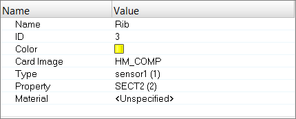
| 6. | In the Model browser, Component folder, click Rib. The Entity Editor opens and displays the component's corresponding data. |
| 7. | For Type, click Unspecified >> ETType. |
| 8. | In the Select ETType dialog, select sensor1 (SHELL181) and then click OK. |
| 9. | For Property, click Unspecified >> Property. |
| 10. | In the Select Property dialog, select SECT2 and then click OK. |
| Note: | You do not have to assign a Property or Material to this component, because this information is already defined in SECT2. |
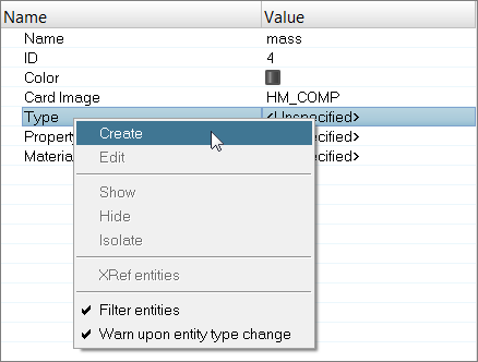
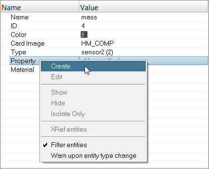
| 11. | In the Model browser, Component folder, click mass. The Entity Editor opens and displays the component's corresponding data. |
| Note: | The mass component does not currently have a type, property, or material attached to it. |
| 12. | For Type, click Unspecified >> ETType. You need to attach the element type MASS21 to the mass component. This element type is not available in the Select ETType dialog because it does not exist in the model, therefore you need to create and attach it to the component. |
MASS21
| • | A point element that can have up to six degrees of freedom: translations in the nodal x, y, and z directions; rotations about the nodal x, y, and z axes. A different mass and rotary inertia may be assigned to each coordinate direction. |
| • | Defined by a single node, concentrate mass components (Force*Time²/Length) in the element coordinate directions and rotary inertias (Force*Length* Time²) about the element coordinate axes. The element coordinate system may be initially parallel to the global Cartesian coordinate system or to the nodal coordinate system (KEYOPT(2)). The coordinate system rotates with the nodal coordinate rotations during a large deflection analysis. Options are available to exclude the rotary inertia effects and to reduce the element to a 2-D capability (KEYOPT(3)). If the element requires only the mass input, it is assumed to act in all appropriate coordinate directions |
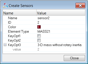
| 14. | Right-click on Type and select Create from the context menu. The Create Sensors dialog opens. |
| 15. | Set Element Type to MASS21. |
| 16. | Set KeyOpt3 to 3-D mass without rotary inertia. |
| 17. | Click Close. HyperMesh creates and attaches the new sensor to the mass component. |
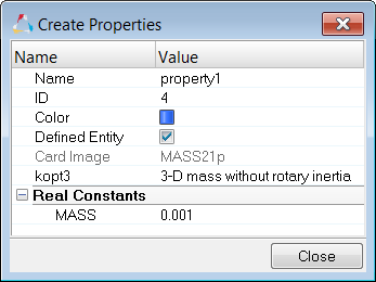
| 18. | Create a property card that associates a small mass to the mass elements by right-clicking on Property and selecting Create from the context menu. |
| 19. | In the Create Properties dialog, the Card Image is automatically set to MASS21p because the element type attached to the mass component is MASS21. |
| 20. | Set KeyOpt3 to 3-D mass without rotary inertia. |
| 21. | Under Real Constants, enter 0.001 for MASS. |
| 22. | Click Close. HyperMesh creates and attaches the new property to the mass component. |
| 23. | For Material, click Unspecified >> Material. |
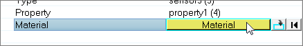
| 24. | In the Select Material dialog, select Steel and then click OK. |
| 25. | The component CERIG contains ANSYS rigid elements. These elements define the rigid region and do not require an element type, property, or material, therefore you do not have to assign a card to this component. |
Step 7: Save your model
| 1. | From the menu bar, click File > Save As > Model. |
| 2. | In the Save Model As dialog, navigate to your working directory and save the file. |
| 3. | To apply boundary conditions and create load steps for your model, proceed to Exercise 2. |
Exercise 2
Introduction to ANSYS Load Steps
This exercise introduces the concept of ANSYS load steps in HyperMesh. In HyperMesh, you need to have each load or constraints in a separate load collector (load cols). With the help of these load collectors, you can create multiple load steps depending on the requirement. The combination of loads with constraints, form a load step. If you have created load steps in your model, the exported *.cdb file will have all of the load step information. This *.cdb file when imported into ANSYS, automatically creates the *.so files in the working directory which can be used later if needed.
In this tutorial, you will learn how to:
| • | Load the ANSYS user profile. |
| • | Retrieve the HyperMesh model file for this tutorial. |
| • | Create constraint load collectors. |
| • | Apply the constraints to the model. |
| • | Apply the force on mass elements with force1 load collector. |
| • | Apply the force on mass elements with force2 load collector. |
| • | Apply the force on mass elements with force3 load collector. |
| • | Create multiple load steps. |
| • | Add /SOLU & LSSOLVE in control cards |
| • | Export the deck to ANSYS *.cdb format |
Optional - Step 1: Load the ANSYS user profile
You only need to perform this step, if you did not complete Exercise 1.
| 2. | In the User Profile dialog, set the user profile to Ansys. |
Optional - Step 2: Retrieve the HyperMesh model file
You only need to perform this step, if you did not complete Exercise 1.
| 1. | From the menu bar, click File > Open > Model. |
| 2. | In the Open Model dialog, open the chapter2_2.hm file. |
| 3. | If you model's elements and mesh lines are not shaded, click on the Visualization toolbar. |
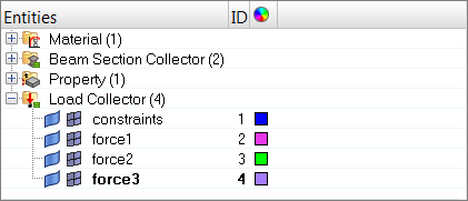
Step 3: Create a constraints load collector
| 1. | In the Model browser, right-click and select Create > Load Collector from the context menu. HyperMesh creates and opens a load collector in the Entity Editor. |
| 2. | For Name, enter constraints. |
| 3. | Click the Color icon, and select a new color for the load collector. |
| 4. | Create three more load collectors labeled force1, force2, and force3. |
Step 4: Apply the constraints to the model
| 1. | In the Model browser, Load Collector folder, right-click on constraints and select Make Current from the context menu. |
| Note: | When new loads are created, Hypermesh will place them in this collector. |
| 2. | Open the Constraints panel by clicking BCs > Create > Constraints from the menu bar. |
| 3. | Select all of the dof (degree of freedom) checkboxes. |
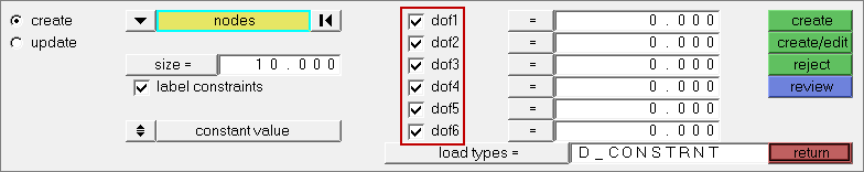
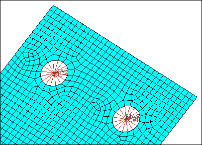
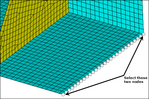
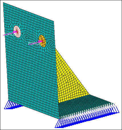
| 4. | Click nodes >> by path. |
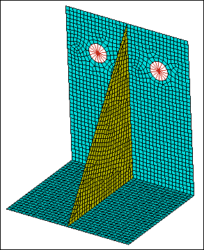
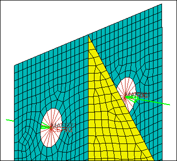
| 5. | Select a starting node and an end node on the left side of the model as indicated in the following image. |
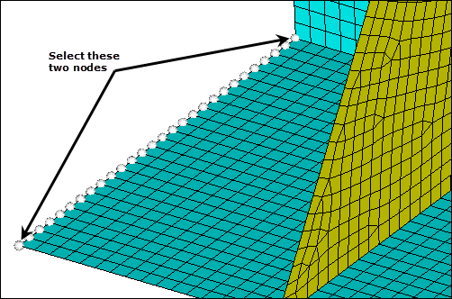
| 7. | Repeat steps 4.4 and 4.5 to select a starting node and an end node on the right side of the model as indicated in the following image. |
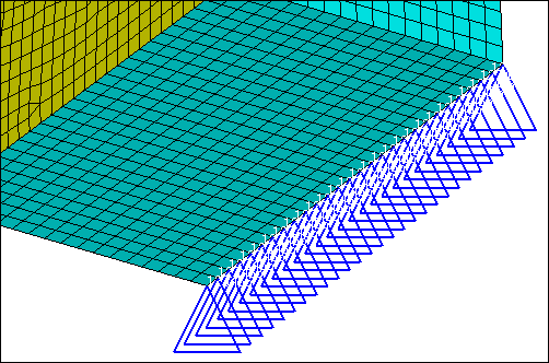
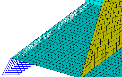
| 9. | Click return to exit the Constraints panel. |
Step 5: Apply the force on mass elements with the force1 load collector
| 1. | In the Model browser, Load Collector folder, right-click on force1 and select Make Current from the context menu. |
| 2. | Open the Forces panel by clicking BCs > Create > Forces from the menu bar. |
| 3. | Verify that the entity selector is set to nodes. |
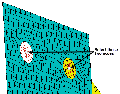
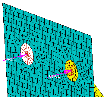
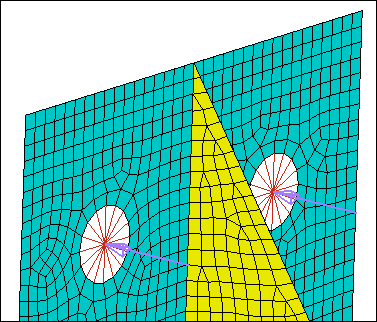
| 4. | Select the two nodes in the center of the two bolt holes as indicated in the following image. |
| 5. | In the magnitude= field, enter 500. |
| 6. | Set the orientation selector to z-axis for the direction of application of the force. |
| 7. | In the uniform size= field, enter 20. |
| 9. | Click return to exit the Forces panel. |
Step 6: Apply the force on mass elements with the force2 load collector
| 1. | In the Model browser, Load Collector folder, right-click on force2 and select Make Current from the context menu. |
| 2. | For better visualization, press F5 to open the Mask panel. |
| 3. | Set the entity selector to loads. |
| 4. | Select the two forces you created in step 5.8. |
| 8. | Verify that the entity selector is set to nodes. |
| 9. | On the Standard Views toolbar, click  . . |
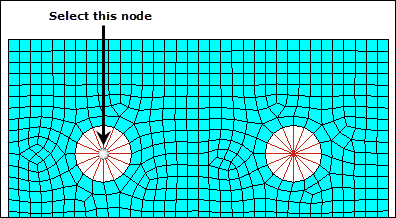
| 10. | Select the left side node in the center of the bolt hole as indicated in the following image. |
| 11. | In the magnitude= field, enter 500. |
| 12. | Set the orientation selector to z-axis for the direction of application of the force. |
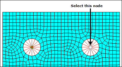
| 14. | Select the right side node in the center of the bolt hole as indicated in the following image. |
| 15. | In the magnitude= field, enter -500. |
| 16. | Set the orientation selector to z-axis for the direction of application of the force. |
| 18. | Click return to exit the Forces panel. |
Step 7: Apply the force on mass elements with the force3 load collector
| 1. | In the Model browser, Load Collector folder, right-click on force3 and select Make Current from the context menu. |
| 3. | Verify that the entity selector is set to loads. |
| 4. | Select the two forces you created in steps 6.13 and 6.17. |
| 8. | Verify that the entity selector is set to nodes. |
| 9. | Select the two nodes in the center of the two bolt holes as indicated in the following image. |
| 10. | In the magnitude= field, enter -500. |
| 11. | Set the orientation selector to z-axis for the direction of application of the force. |
| 13. | Click return to exit the Forces panel. |
Step 8: Create multiple load steps
| 1. | In the Model browser, right-click and select Create > Load Step from the context menu. HyperMesh creates and opens a load step in the Entity Editor. |
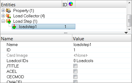
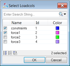
| 3. | For Loadcol IDs, click 0 Loadcols >> Loadcols. |
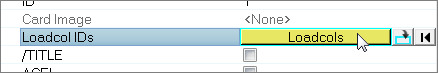
| 4. | In the Select Loadcols dialog, select constraints and force1. |
| 6. | Create a second load step labeled Step2, and assign it the load collectors constraint and force2. |
| 7. | Create a third load step labeled Step3, and assign it the load collectors constraint and force3. |
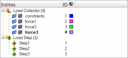
| 8. | In the Model browser, review the Load Collectors and Load Steps you created. |
| 9. | Open the Solver browser by clicking View > Browsers > HyperMesh > Solver from the menu bar. |
| 10. | Review the Load Collectors and Load Steps you created. |
Step 9: Add /SOLU, ANTYPE, and LSSOLVE in the control cards
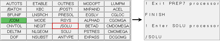
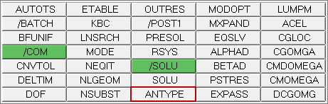
| 1. | Open the Control Cards panel by clicking Setup > Create > Control Cards from the menu bar. |
| 2. | In the Card Image, click /SOLU to exit the PREP7 preprocessor and enter the SOLU preprocessor. |
| 4. | Because you are solving the model for static analysis, click ANTYPE. |
| 5. | Set type to STATIC and status to NEW. |
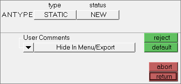
| Tip: | If you do not see the LSSOLVE control card, click next. |
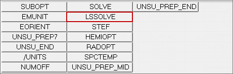
| 8. | Set the minimum number of load steps by entering 1 in the LSMIN field. |
| 9. | Set the maximum number of load steps by entering 3 in the LSMAX field. |
| 10. | Set the load step increment by entering 1 in the LSINC field. |
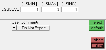
This card image commands the solver to solve all three load steps.
| 11. | Click return to exit the card image. |
| 12. | Click return to exit the Control Cards panel. |
Step 10: Export the deck to ANSYS *.cdb format.
| 1. | Open the Export tab by clicking File > Export > Solver Deck from the menu bar. |
| 2. | Set File type to Ansys. |
| Note: | If you are in the ANSYS user profile, HyperMesh automatically sets the File type to Ansys and loads ANSYS as the default Template. |
| 3. | In the File field, navigate to your working directory and save the file as 4410_export.cdb. |
See Also:
HyperMesh Tutorials


