Objective
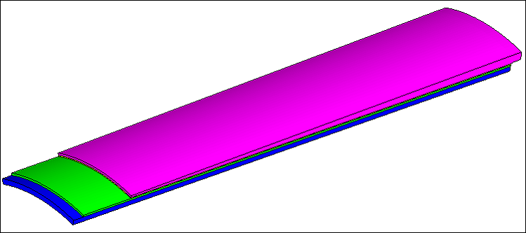
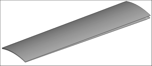
Use morphing to change the thickness of the middle layers of a four-layered solid, while maintaining the thickness of the outer layers.
Model Files
This exercise uses the Morph_Adhesive_Layers.hm file, which can be found in the hm.zip file. Copy the file(s) from this directory to your working directory.
Tools
Domains will be created using 3D domains > by component. Thickness will be altered using alter dimensions.
Step 1: Open the file.
| 1. | Open the file, Morph_Adhesive_Layers.hm. |
Step 2: Create domains and handles.
| 1. | Click the Morphing menu and pick Create > Domains. |
| 2. | Switch the domain type to 3D domains. |
| 3. | Toggle the element selector to all elements. |
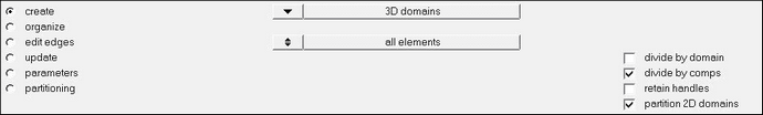
| 4. | Activate the divide by comps and partition 2D domains options. The panel should appear as in the following image: |
| 5. | Click create to create the domains. |
| 6. | Click return to exit the Domains panel. |
Step 3: Display only the morph faces of interest.
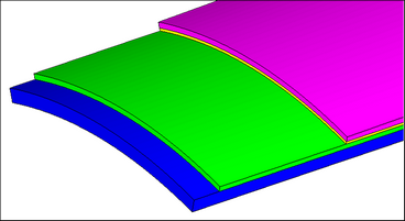
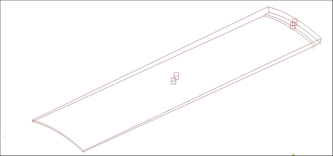
| 1. | Using the Model Browser, hide all the components except ^morphface. |
| 2. | Mask all ^morphface elements except those on the outer layer and the layer between the Outer comp and the Adhesive_Outer to leave all the elements shown in the following image. |
| HINT: | Select a couple of elements on the face you want to keep. Select elements >> by face, and then select elements >> reverse. This will reverse the selection to the elements you do not want and will allow you to mask those elements with the mask button. |
| 3. | To reduce the number of domains and handles shown on the screen, click the Mask tab. |
| 4. | Click the + next to Morphing to expand it. |
| 5. | Click the + in the Show column for Local Domains/Handles to display the domains and handles for only the displayed elements. |
| 6. | Hide the ^morphface component in the Model Browser. |
Step 4: Increase the thickness of the outer adhesive layer by 5 units.
| 1. | Click the Morphing menu and pick Morph to open the Morph panel. |
| 2. | Open the alter dimensions subpanel. |
| 3. | Change the dimension type to radius. |
| 4. | Activate the add to current checkbox. |
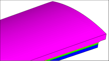
| 5. | For domains, select the curved edge domains as well as the 2-D domains representing the curved surfaces as seen in the following image. |

| 6. | Set the center calculation to by axis. |
| 7. | For the axis, use the z-axis. |
| 8. | For B select the temp node that represents the center of the cylinder. |
| 9. | In radius= box, change value to 5 units. |
| 11. | Go to the save shape subpanel. |
| 13. | Switch to as node perturbations. |
| 15. | Click undo all to revert back to the original model configuration. |
| 16. | Show all components except the ^morphface component. |
| 17. | Go to the apply shapes subpanel. |
| 18. | For shapes select sh1. |
This takes you to the Deformed Shape panel.
| 21. | Change the animation scale from model units to scale factor. |
| 22. | Set the scale factor to 1. |
| 23. | Click linear to start the animation. |
| 24. | Once you are done viewing your animation and verifying that it is as intended, you can return to the main panel area. |
With this step you have successfully completed morphing one of the middle layers of the four-layer model.
Optional: Using the process shown above, increase the thickness of Adhesive_Inner component by 5 units.
See Also:
HyperMesh Tutorials


