Model Files
This exercise uses the yoke.hm file, which can be found in the hm.zip file. Copy the file(s) from this directory to your working directory.
Exercise: Morphing a Yoke via Morph Volumes and Shapes
In this exercise you will increase the diameter of one of the prongs of a yoke using morph volumes. You will reflect the shape on to the other prong and finally position the combined shapes from one yoke to the other.
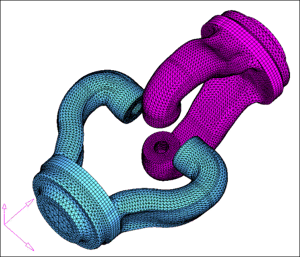
Figure 1: Yoke model
Step 1: Load and review the model.
| 1. | Open the HyperMesh file yoke.hm. |
| 2. | In the Model Browser, right-click component yoke_2, then select Hide; make sure component yoke_1 is in Show mode. |
Step 2: Convert hexas to morph volume.
| 1. | From the menu bar, select Morphing > Create > Morph Volumes, then select the convert subpanel. |
| 2. | Select elems >> by collector. |
| 3. | Select hexas. Make sure that register all inner nodes is checked. |
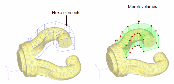
Figure 2: Converting hexas volumes to morph volumes
| Note: | All the seven hexa elements are converted into morph volumes. |
Step 3: Increase the prong diameter.
| 1. | In the Model Browser, right-click Tag and select Show to display all the tags. |
| 2. | From the menu bar, select Morphing > Morph, then select the move handles subpanel. |
| 3. | Set the mode selector to move to node. |
| 4. | Click options and make sure morphing>mvols: is set to active (toggle if it is set to inactive). |
| 6. | For handle, click Handle 1, and for node, click tag 1’. |
| 7. | Repeat this process for the other 35 handles. |

Figure 3: Using tags to change the morph volumes
Step 4: Save the morphed shape.
| 1. | From the menu bar, select Morphing > Create > Shapes. |
| 2. | Go to the save as shape subpanel. |
| 3. | For name=, enter Prong1. |
| 4. | Toggle as handle perturbations to as node perturbations. |
| 5. | Click create and select Yes to the message which appears. |
| 6. | Click undo all to bring the model to its original position before morphing. |
Step 5: Create coordinate system.
You need to reference a coordinate system in order to create symmetry.
| 1. | In the Model Browser, right-click and select Hide for Shape and Morphing Volume. Right click on yoke_1 and select Show. |
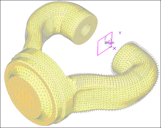
| 2. | From the menu bar, select Geometry > Create > Systems > Axis Direction to open the Systems panel, create by axis direction subpanel. |
| 3. | Click origin and select the node labeled "origin." |
| 4. | For X-axis, select the node labeled "X." |
| 5. | For XY plane, select the node labeled "Y." |
Step 6: Create symmetry.
| 1. | From the menu bar, select Morphing > Create > Symmetries. |
| 2. | For name =, enter symm1. |
| 3. | Under domains, click the check-box for morph volumes. (make sure it is active). |
| 4. | Set 1 plane and keep the rest of the default settings. |
| 5. | Click syst and select the newly created coordinate system. |
Step 7: Reflect shape.
| 1. | From the menu bar, select Morphing > Create > Shapes. |
| 2. | Change the subpanel to apply shapes. |
| 3. | Under shapes, change apply shapes to reflect shapes. |
| 4. | Change apply only to apply & create. |
| 5. | Keep the default auto-envelope. |
| 6. | Click shapes and select the newly created shape from the previous section. |
| 7. | Under reflect using: click symmetries and select the newly created symmetry. |
| Note: | A reflected shape has been created and applied on the other prong. |
The name of the shape, created by reflecting, has the same name as the original shape with a suffix “1.”
Step 8: Position the shapes onto the other yoke.
In this step, you will position the shapes of the two prongs of the yoke onto the opposite yoke.
| 1. | In the Model Browser, right-click Title and select Show. |
| 2. | In the Model Browser right-click yoke_2 and click Show. |
| 3. | In the apply shapes subpanel, under shapes, change reflect shapes to position shapes. |
| 4. | Change the selector from scale to no scale. |
| 5. | Click shapes and select the two shapes present in the model. |
| 6. | Under from: select the three nodes named from_N1, from_N2 and from_N3 for N1, N2 and N3. |
| 7. | Under to: select the three nodes named to_N1, to_N2 and to_N3 for N1, N2 and N3. |
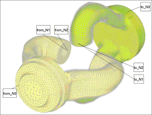
| Note: | The two or more shapes have been created and applied to the other yoke. The name of the first new shape (on the other yoke) will have a suffix “2” because it is the second copy of the first shape and the second shape will have a suffix of “11” as it is the first copy of the reflected shape. |
See Also:
HyperMesh Tutorials


