Model Files
This exercise uses the truck.hm file, which can be found in the hm.zip file. Copy the file(s) from this directory to your working directory.
Exercise: Using Cluster Constraints to Preserve the Wheel Shape while Lengthening the Body of a Truck
When circular features are stretched, they become elliptical in shape. In some cases as in the wheels of a truck, this effect is not desirable. In such cases, using cluster constraints will allow you to translate the features, along with the morph, while maintaining its circular shape.
In the exercise you will be changing the length of the cab while preserving the shape of the wheel. To facilitate the morphing process you will be employing constraint and symmetry.
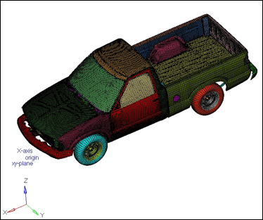
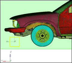
Figure 1: Truck model
Step 1: Load and review the model.
Open the HyperMesh file truck.hm.
Step 2: Create a coordinate system.
| 1. | Using the menu bar select Geometry > Create > Systems > Axis Direction. |
| 2. | For origin select the node with tag origin. |
| 3. | For x-axis, select node with tag x-axis. |
| 4. | For xy-plane, select node with xy-plane. |
| 5. | Click create to create the coordinate system. |
| 6. | On the toolbar, select XZ Right Plane View ( ) ) |
| 7. | Click return to exit the panel. |
Step 3: Create and split the morph volume.
| 1. | From the menu bar select Morphing > Create > Morph Volumes. |
| 2. | Switch the creation method to create morphvol. |
| 3. | Set entity type to enclose elements. |
| 5. | Set system to global system. |
The morph volume is created.
| 7. | Click create to create the morph volume. |
| 8. | Click the split/combine subpanel. |
| 9. | Toggle the operation to split mvols. |
| 10. | Toggle to split the morph volume by edges. |
| 11. | Toggle the type of split to single split. |
| 12. | Set single split = 0.44. |
| 13. | Select the morph volume in the graphics window. |
| 14. | Click split to split the morph volume. |
The original morph volume is now split into two morph volumes.
| 15. | Click return to exit the panel. |
Step 4: Create a Symmetry.
| 1. | From the menu bar select Morphing > Create > Symmetries: |
| 2. | For name =, enter symm1. |
| 3. | Under domain, check the box for morph volumes. |
Symmetry can be linked to either domains or morph volumes. In this exercise since you are dealing with morph volumes you will use the check to link the symmetry to the morph volume.
| 4. | Switch the symmetry type to 1 plane. |
| 5. | For syst, select the coordinate system created in step 4.2. |
| 6. | Click create to create the symmetry. |
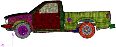
A 1 plane symmetry with a square symbol has been created.
| 7. | Click return to exit the panel. |
Step 5: Morph the part.
| 1. | From the menu bar select Morphing > Morph, then click the move handles subpanel. |
| 2. | Switch the morphing mode to translate. |
| 3. | Switch the along option to along xyz. |
| 4. | Set the following values: |
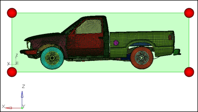
| 5. | Select two handles as shown in figure 3. |
| 6. | Click morph to morph the front half of the truck. |
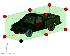
Figure 2.1 Front half of the truck to morph
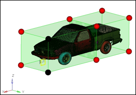
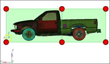
Figure 2.2 Front half of the truck morphed
The front end is stretched 500 units. Since the front wheels are also the part of the morph volumes they became elliptical after morphing. This is not desirable. You will undo this morphing, constrain the wheels and re-do it.
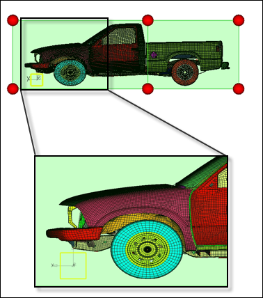
Figure 3: undesired morphing of the front wheel
Step 6: Create a cluster constraint.
As seen in the previous image, the front wheels, after morphing, become elliptical. To fix this issue, you will be employing a particular type of constraint, called a cluster constraint, which helps to keep the original shape of a portion of the model while morphing.
| 1. | From the menu bar select Morphing > Create > Morph Constraints. |
| 3. | Switch the constraint type to cluster. |
| 4. | Select nodes >> by collector . |
| 6. | Use id = 1-8 and then hit ENTER on the keyboard. |
| 7. | Click select to select the components. |
| 8. | Click create to create the cluster constraint. |
The cluster constraints are created on the nodes of the selected components.
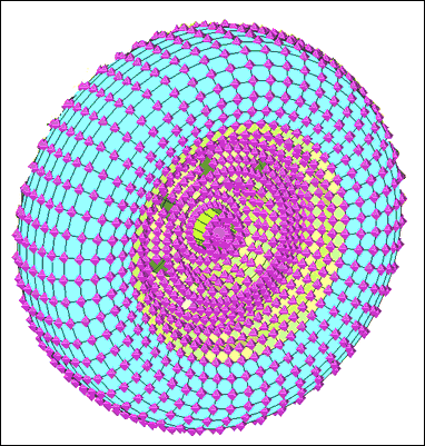
Figure 4
| 9. | Click return to exit the panel. |
| 10. | In the Model Browser, right-click MorphingConstraint and click Hide to turn off the constraints. |
Step 7: Morph the part.
| Repeat the procedure in Step 5 to morph the front of the truck by 500 units. |
The front end is stretched 500 mm. The front wheels are moved in the morphing process while maintaining their circular shape.
Summary
Using cluster constraints and morph volumes you are able to stretch the cab of the pickup without distorting the wheels.
See Also:
HyperMesh Tutorials


