Definition
The two beam elements available in RADIOSS are used on one-dimensional structures and frames. It carries axial loads, shear forces, bending and torsion moments (contrary to the truss that supports only axial loads).
The default formulation is based on the Timoshenko formulation; therefore, transverse shear strain is taken into account. This formulation can degenerate into the standard Euler-Bernoulli formulation, where transverse shear energy is neglected.
Nodes 1 and 2 are used to define the local x-axis. Local y-axis is normal to the x-axis and is in the plane defined by node 1, 2 and 3 at time t=0. Then its position is corrected at each cycle, taking into account the mean x-rotation. Local z-axis is obtained using the right-hand rule.
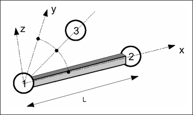
Fig. 2.11: Beam element and local system
In RADIOSS, the beam geometry is defined by its cross-section area and by its three cross-section moments of inertia. The moments of inertia around local Y-axis and Z-axis are for bending and they can be calculated using the following formulas:
The moment of inertia regarding the local X-axis is for torsion. It can simply be obtained by the summation of ly and lz. The torsion model is only valid for full cross-section where the warping is neglected.
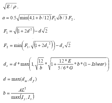
The minimum time step for a beam element is determined using the following equation:
Where, c is the speed of sound:
User input parameters to define beam cross-section are the three moments of inertia and the area. For accuracy and stability, it is recommended to respect the following limitations:
Only material Laws 1 and 2 are available for this beam element. A global plasticity model in function of internal forces is used in Law 2. The main assumption is that the beam cross-section is full and rectangular. Optimal interaction between section and section inertia are:
This model also provides good results for circular or ellipsoidal cross-section. For thin-walled cross-sections, the global plasticity model may provide incorrect results. It is not recommended to use a single beam element per line of frame structure. The mass is lumped onto the nodes; therefore, to get a correct mass distribution, a fine mesh is required. This is especially true when dynamic effects are important.
Moreover, in RADIOSS beam element, the moment does not vary along the beam length. The moment is supposed constant and is evaluated at the beam center, as is the stress.
Consequently, a beam will yield at a slightly higher force in the case of a clamped cantilever beam, since the moment is calculated at the center, instead of at the root of the beam.
| Note: | Output for beam elements are expressed in the local system. Some results may be confusing, due to the fact that the local system is updated taking into account the mean X rotation. For instance, a beam with one node completely blocked, if an axial rotational velocity V is imposed to the other node, then the beam will rotate at a speed of V, but the local system will rotate at a speed of V/2. This may lead to a bad interpretation of results, especially the shear forces and bending moments. |
|
The cross-section of the element is defined using up to 100 integration points (Fig. 2.12). The element properties of the cross-section, that is moments of inertia and area, are computed by RADIOSS as:
Beam model is based on the Timoshenko theory and takes into account transverse shear strain without warping in torsion. It can be used for deep beam cases (short beams). The use of several integration points in the section allows to get an elasto-plastic model, in which von Mises criteria is written on each integration point and the section can be partially plastified contrary to the classical beam element (Type 3). Material Law 36 is also available, as well as Law 1 and Law 2. However, as the element has only one integration point in its length, it is not recommended to use a single beam element per line of frame structure in order to take into account the plasticity progress in length, as well as in depth.
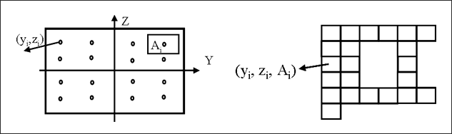
Fig. 2.12: Cross-section definitions in the integrated beam


