|
»Click here to display Table of Contents«
|

CBUSH |

|

|

|

|
|
CBUSH |
|
|

|

|
|
»Click here to display Table of Contents«
|
CBUSH |
|
|
|
|
|
CBUSH |
|
|
|
|
Bulk Data Entry
CBUSH – Bushing Element
Description
Defines a generalized spring-damper structural element.
Format
(1) |
(2) |
(3) |
(4) |
(5) |
(6) |
(7) |
(8) |
(9) |
(10) |
CBUSH |
EID |
PID |
GA |
GB |
G0/X1 |
X2 |
X3 |
CID |
|
|
S |
OCID |
S1 |
S2 |
S3 |
|
|
|
|
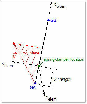
Spring-damper element defined with default orientation and location; default orientation is only valid when only K1, and/or K4 are defined on referenced PBUSH.
|
Spring-damper location is offset from mid-point of GA-GB.
|
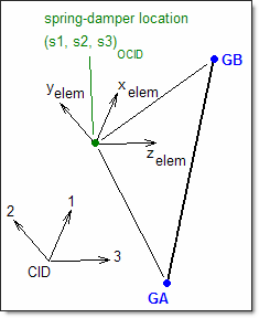
Spring-damper is oriented by referencing coordinate system 5, and spring-damper location is explicitly defined using OCID, S1, S2, and S3.
|
Field |
Contents |
EID |
Unique element identification number. No default (Integer > 0) |
PID |
PBUSH entry property identification number. Default = EID (Integer > 0) |
GA |
Grid point identification number of the first connection point. No default (Integer > 0 or <PartName.number>) See comments 6, 9 and 10. |
GB |
Grid point identification number of the second connection point. No default (Integer > 0 or <PartName.number>) See comments 6, 9 and 10. |
Xi |
Components of orientation vector (Real) |
G0 |
Alternate method to supply vector (Integer > 0 or <PartName.number>) See comments 3 and 9. |
CID |
Element coordinate system identification. If 0, the basic coordinate system. If blank, the element coordinate system is determined from GO or Xi. (Integer > 0 or blank) See comments 2 and 3. |
S |
Location of spring-damper as a fraction along the line segment between GA and GB. Default = 0.5 (0.0 < Real < 1.0) |
OCID |
Coordinate system identification for spring-damper offset. See comment 7. Default = -1 (Integer > -1; -1 indicates that the offset is along GA-GB) |
Si |
Components of the spring-damper offset in the OCID coordinate system, ignored if OCID is -1. (Real) |
| 1. | Element identification numbers must be unique with respect to all other element identification numbers. |
CBUSH element
Alternate CBUSH element definition
| 2. | CID > 0 overrides GO and Xi. Then the element x-axis is along T1, the element y-axis is along T2, and the element z-axis is along T3 of the CID coordinate system. If the CID refers to a cylindrical coordinate system or a spherical coordinate system, the grid GA is used to locate the system. If for cylindrical or spherical coordinate, GA falls on the z-axis used to define them, it is recommended that another CID be selected to define the element x-axis. |
| 3. | For noncoincident grids (GA ≠ GB), when GO or (X1, X2, X3) is given and no CID is specified, the line AB is the element x-axis and the orientation vector |
| 4. | For noncoincident grids (GA ≠ GB), if neither GO or (X1, X2, X3) is specified and no CID is specified, the line AB is the element x-axis. This option is valid only when K1 or K4 or both on the PBUSH entry are specified (but K2, K3, K5, and K6 are not specified). If K2, K3, K5, or K6 are specified, the solver will terminate with an error. |
| 5. | If GA and GB are coincident, or if GB is blank, CID must be specified. If GB is set to blank, the CBUSH simulates a grounded bushing element. |
| 6. | If OCID refers to a cylindrical or spherical coordinate system, then grid GA is used to locate the system. |
| 7. | A CBUSH element, referencing a PBUSH property with a single stiffness term, is equivalent to a CELAS1 or CELAS2 element, only when the elements have zero length. A non-zero length CBUSH assumes rigid body connections from the connection points, GA and GB, to the spring-damper location, as defined either by S or the OCID and Si fields. |
| 8. | Bushing elements are ignored in heat transfer analysis. |
| 9. | Supported local entries in specific parts can be referenced by the use of “fully qualified references” on CBUSH entries in the model. A fully qualified reference (“PartName.number”) is similar to the format of a numeric reference. “PartName” is the name of the part that contains the referenced local entry (part names are defined on the BEGIN Bulk Data Entry in the model). “number” is the identification number of a referenced local entry in the part “PartName”. See Parts and Instances in the User’s Guide for detailed information on the use of fully qualified references. |
| 10. | The CBUSH element force is calculated as follows: |
F = K(UGB - UGA)
Therefore, the sign of the force will depend on the grids GA and GB. If the grids are switched, the element force will be reversed.
| 11. | This card is represented as a spring element in HyperMesh. |
See Also: