HyperWorks Solvers

Ityp = 2

Ityp = 2

Previous topic Next topic Expand/collapse all hidden text  

Ityp = 2

Previous topic Next topic JavaScript is required for expanding text JavaScript is required for the print function  

Block Format Keyword

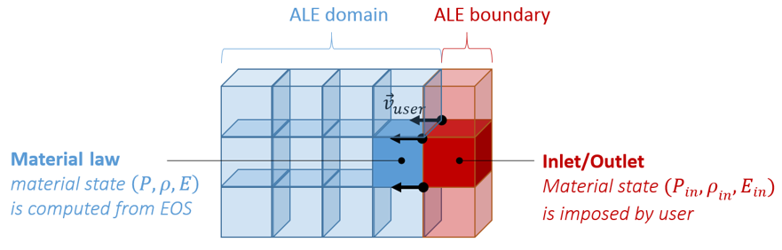
/MAT/B-K-EPS - ITYP=2 - Boundary Conditions Material for Flow Analysis with Turbulence

Description

This law enables to model a material inlet/outlet by directly imposing its state. Input card is similar to /MAT/LAW11 (BOUND), but introduces two new lines to define turbulence parameters.

law11_ityp2

Format

(1)

(2)

(3)

(4)

(5)

(6)

(7)

(8)

(9)

(10)

/MAT/B-K-EPS/mat_ID

mat_title


Ityp


Psh

FscaleT


Ityp =2 – General Inlet/Outlet

(1)

(2)

(3)

(4)

(5)

(6)

(7)

(8)

(9)

(10)

Blank Format

fct_IDρ


fct_IDp


P0


fct_IDE


E0


fct_IDk

fct_IDε


csymbol_u

Pr / Prt


fct_IDT

fct_IDQ


hmtoggle_plus1Flag Definition

Field

Contents

SI Unit Example

mat_ID

Material identifier

(Integer, maximum 10 digits)


mat_title

Material title

(Character, maximum 100 characters)


Initial density (Comment 3)

(Real)

Reference density used in E.O.S (equation of state)

Default (Real)

Ityp

Boundary condition type (Comment 1)

(Integer)

= 0: gas inlet (from stagnation point data)

= 1: liquid inlet (from stagnation point data)

= 2: general inlet/outlet

= 3: non-reflecting boundary


Psh

Pressure shift (Comment 2)

(Real)

symbol_Pa

FscaleT

(Optional) Time scale factor (Comment 3)

(Real)


fct_IDρ

(Optional) Function identifier for boundary density (Comment 3)

(Integer)

= 0:

> 0:


fct_IDp

(Optional) Function identifier for boundary pressure (Comment 3)

(Integer)

= 0:

> 0:


P0

Initial pressure (Comment 3)

(Real)

symbol_Pa

fct_IDE

Function identifier for boundary energy (Comment 3)

(Integer)

= 0:

> 0:


E0

Initial energy (Comments 3 and 6)

(Real)

symbol_Pa

Initial turbulent energy

(Real)

symbol_J

Initial turbulent dissipation

(Real)

symbol_J

fct_IDk

(Optional) Function identifier for turbulence modeling

(Integer)

= 0:

> 0:


fct_IDε

(Optional) Function identifier for energy

(Integer)

= 0:

= n:


csymbol_u

Turbulent viscosity coefficient

Default = 0.09  (Real)


Diffusion coefficient for k parameter

Default = 1.00  (Real)


Diffusion coefficient for ε parameter

Default = 1.30  (Real)


Pr / Prt

Ratio between Laminar Prandtl number (Default 0.7) and turbulent Prandtl number (Default 0.9).

(Real)


fct_IDT

Function identifier for inlet temperature

(Integer)

= 0: T = Tadjacent

= n:


fct_IDQ

Function identifier for inlet heat flux

(Integer)

= 0: no imposed flux

= n:


hmtoggle_plus1Example (Gas)

#RADIOSS STARTER

#---1----|----2----|----3----|----4----|----5----|----6----|----7----|----8----|----9----|---10----|

/MAT/B-K-EPS/3

GAS INLET (unit: kg_m_s)

#              RHO_I

               .3828

#     ITYP                           Psh         Fscale_T

         2

#blank line


#  fct_RHO

         1

#    fct_P                           P_0

         0

#    fct_E                           E_0

         1                        253300

#             Rho0k0            Rho0Eps0     fct_k   fct_eps

                  20                   0         1         0

#                Cmu             Sigma-k       Sigma-epsilon              Pr/Prt

                   0                   0                   0                   0

# fct_T        fct_Q


/ALE/MAT/3

#     Modif. factor.

                   0

#---1----|----2----|----3----|----4----|----5----|----6----|----7----|----8----|----9----|---10----|

/FUNCT/1

CST

#                  X                   Y

                   0                   1

              1.0E20                   1

#---1----|----2----|----3----|----4----|----5----|----6----|----7----|----8----|----9----|---10----|

#enddata

/END

#---1----|----2----|----3----|----4----|----5----|----6----|----7----|----8----|----9----|---10----|

hmtoggle_plus1Comments
1.Provided state is directly imposed to inlet boundary elements. This leads to the following inlet state:

With this formulation, you may impose velocity on boundary nodes to be consistent with physical inlet velocity (/IMPVEL). /MAT/LAW11 – ITYP=0 and 1, are based on material state from stagnation point, where you do not need to imposed an inlet velocity.

2.The PSH parameter enables shifting the output pressure which also becomes P-PSH. If using PSH=P(t=0), the output pressure will be symbol_dp, with an initial value of 0.0.
3.If no function is defined, then related quantity remains constant and set to its initial value. However, all input quantities can be defined as time dependent function using provided function identifiers. Abscissa functions can also be scaled using FscaleT parameter which leads to use f (Fscalet * t) instead of f(t).
4.With thermal modeling, all thermal data (, …) can be defined with /HEAT.
5.It is not possible to use this boundary material law with multi-material ALE laws 37 (BIMAT) and 51 (MULTIMAT).
6.Specific volume energy E is defined as E = Eint / V, where Eint is the internal energy. It can be output using /TH/BRIC.

Specific mass energy e is defined as e = Eint / m. This leads to . Specific mass energy e can be output using /ANIM/ELEM/ENER. This may be a relative energy depending on user modeling.

See Also:

Material Compatibility