|
»Click here to display Table of Contents«
|

CGASK6 |

|

|

|

|
|
CGASK6 |
|
|

|

|
|
»Click here to display Table of Contents«
|
CGASK6 |
|
|
|
|
|
CGASK6 |
|
|
|
|
Bulk Data Entry
CGASK6 – Five-sided Solid Gasket Element with Six Grid Nodes
Description
Defining the connections of the GASK6 solid gasket element.
Format
(1) |
(2) |
(3) |
(4) |
(5) |
(6) |
(7) |
(8) |
(9) |
(10) |
CGASK6 |
EID |
PID |
G1 |
G2 |
G3 |
G4 |
G5 |
G6 |
|
|
CORDM |
CID |
|
|
|
|
|
|
|
|
Field |
Contents |
EID |
Unique element identification number. No default (Integer > 0) |
PID |
Identification number of a PGASK property entry. Default = EID (Integer > 0) |
G# |
Grid point identification number of connection points. No default (Integer > 0) |
CORDM |
Flag indicating that the following field references the material coordinate system. |
CID |
Identification number of the material coordinate system. Default = 0 (Integer ≥ -1) |
| 1. | Grid points G1, G2, G3 must be given in consecutive order at the bottom face of the gasket element. G4, G5, G6 must be on the top face with G4 opposite G1, G5 opposite G2, and G6 opposite G3. |
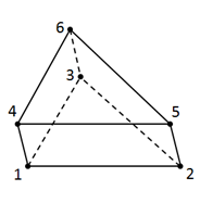
| 2. | If the user-defined node numbering on the bottom and top faces is reversed as compared to the sequence shown above, the nodes are renumbered to produce right-handed orientation of numbering. This is accomplished by swapping nodes G1 with G3, and G4 with G6. In such cases, the element local coordinate system will be built on the renumbered node sequence. |
| 3. | The element coordinate system for the CGASK6 element is defined below. |
The local 3-direction (the gasket material thickness direction in default) is defined as the simple average of the unit normal directions on the top and bottom surfaces of the element. After the local 3-direction is defined, a local 1-2 plane is generated accordingly.
Then, the local 1-direction and 2-direction are defined as follows: Project the basic x-axis onto the local 1-2 plane, and set it to be the default local 1-direction. If the basic x-axis is within 0.1° difference as the local 3-direction, project the basic z-axis onto the local 1-2 plane and set it to be the local 1-direction. The local 2-direction is determined then.
| 4. | The gasket material coordinate system is the same as the element coordinate system by default. This can be modified to represent a user-defined coordinate system using the PGASK entry. |
| 5. | This card is represented as a gask6 element in HyperMesh. |
See Also: