|
»Click here to display Table of Contents«
|

CHEXA |

|

|

|

|
|
CHEXA |
|
|

|

|
|
»Click here to display Table of Contents«
|
CHEXA |
|
|
|
|
|
CHEXA |
|
|
|
|
Bulk Data Entry
CHEXA – Six-sided Solid Element with Eight or Twenty Grid Points
Description
Defines the connections of the HEXA solid element.
Format
(1) |
(2) |
(3) |
(4) |
(5) |
(6) |
(7) |
(8) |
(9) |
(10) |
CHEXA |
EID |
PID |
G1 |
G2 |
G3 |
G4 |
G5 |
G6 |
|
|
G7 |
G8 |
G9 |
G10 |
G11 |
G12 |
G13 |
G14 |
|
|
G15 |
G16 |
G17 |
G18 |
G19 |
G20 |
|
|
|
|
CORDM |
CID |
|
|
|
|
|
|
|
|
Field |
Contents |
EID |
Unique element identification number. No default (Integer > 0) |
PID |
A PSOLID property entry identification number. Default = EID (Integer > 0) |
G# |
Grid point identification numbers of connection points. Default = blank (Integer > 0 or blank) |
CORDM |
Flag indicating that the following field references the material coordinate system. |
CID |
Identification number of the material coordinate system. Default = 0 (Integer ≥ -1) |
| 1. | Grid points G1, …, G4 must be given in consecutive order about one quadrilateral face. G5, …, G8 must be on the opposite face with G5 opposite G1, G6 opposite G2, and so on. |
The edge points, G9 through G20, are optional, some or all of them may be blank. If any of the edge points are present, they all must be used. The second continuation must not be present for the 8-noded version of this element.
It is recommended that the edge points be placed near the middle of the edge.
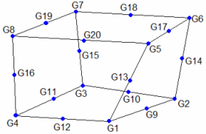
CHEXA definition
| 2. | If the user-defined node numbering on the bottom and top faces is reversed as compared to the sequence shown above, the nodes are renumbered to produce right-handed orientation of numbering. This is accomplished by swapping nodes G1 with G3, and G5 with G7. For 20-noded CHEXA, appropriate changes to mid-side node numbering are also performed. In such cases, the element coordinate system will be built on the renumbered node sequence. |
| 3. | Stresses are output in the material coordinate system. The material coordinate system is defined on the referenced PSOLID entry. It may be defined as the basic coordinate system (CORDM = 0), a defined system (CORDM = Integer > 0), or the element coordinate system (CORDM = -1). |
| 4. | The element coordinate system for the CHEXA element is defined as follows: |
Three intermediate vectors R, S, and T are chosen by the following rules:
R |
Joins the centroids of the faces described by the grid points G4, G1, G5, G8 and the grid points G3, G2, G6, G7. |
S |
Joins the centroids of the faces described by the grid points G1, G2, G6, G5 and the grid points G4, G3, G7, G8 |
T |
Joins the centroids of the faces described by the grid points G1, G2, G3, G4 and the grid pints G5, G6, G7, G8. |
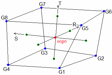
CHEXA element coordinate systems
The origin of the element coordinate system is at the intersection of these three vectors. If the vectors do not all intersect at one point, then the average location of the intersection points is used.
The element z-axis corresponds to the T vector.
The element y-axis is the cross product of the T and R vectors.
The element x-axis is the cross product of the element y-axis and the element z-axis.
| 5. | This card is represented as a hexa8 or hex20 element in HyperMesh. |
See Also: