|
»Click here to display Table of Contents«
|

CHBDYE |

|

|

|

|
|
CHBDYE |
|
|
|

|
|
»Click here to display Table of Contents«
|
CHBDYE |
|
|
|
|
|
CHBDYE |
|
|
|
|
CHBDYE – Thermal Surface Element (Element Form)
Defines a surface element for application of thermal boundary condition.
(1) |
(2) |
(3) |
(4) |
(5) |
(6) |
(7) |
(8) |
(9) |
(10) |
CHBDYE |
EID |
EID2 |
SIDE |
|
|
|
|
|
|
Field |
Contents |
EID |
Unique surface element identification number. No default (Integer > 0) |
EID2 |
A heat conduction element identification number (Comment 1). No default (Integer > 0) |
SIDE |
Element side identification number. No default (1 < Integer < 6) |
Comments
| 1. | EID2 identifies the heat conduction element associated with this surface element. |
1D |
2D |
3D |
|---|---|---|
CBAR |
CQUAD4 |
CHEXA |
CBEAM |
CQUAD8 |
CPENTA |
CONROD |
CTRIA3 |
CPYRA |
CROD |
CTIRA6 |
CTETRA |
Conduction elements for heat transfer analysis
| 2. | All conduction elements that are to have a boundary condition applied must be individually identified with the application of a surface element entry CHBDYE. |
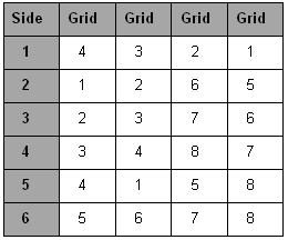
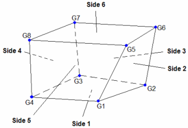
| 3. | Side conventions for 3D elements: |
Sides are numbered consecutively according to the order of the grid point numbers on the 3D element entry. The sides of 3D elements are either quadrilaterals or triangles. For each element type, the side numbers are shown here:
|
|
Side convention for CHEXA element (1st or 2nd order)
|
|
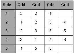
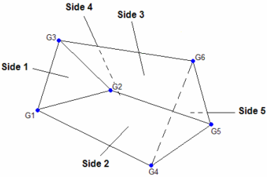
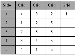
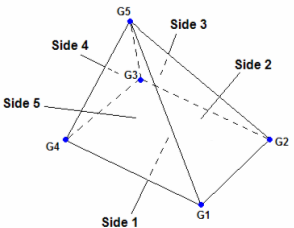
Side convention for CPENTA element (1st or 2nd order)
|
|
Side convention for CPYRA element (1st or 2nd order)
|
|
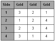
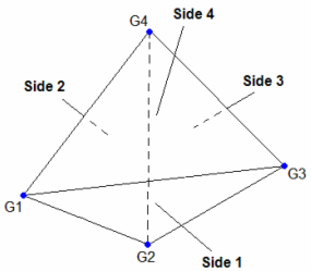
Side convention for CTETRA element (1st or 2nd order)
| 4. | Side conventions for 2D elements. |
2D elements have one side of type AREA (this is Side 1) and 3 or 4 sides of type LINE.
AREA type: Side 1 is that given by the right hand rule on the shell’s gird points.
LINE type: The second side (first line) is from grid point 1 to grid point 2, and the remaining lines are numbered consecutively. The thickness of the line is that of the shell, and the normal to the line is outward from the shell in the plane of the shell. Note that midside nodes are ignored in the specification.
| 5. | Side conventions for 1D elements. |
1D elements have one linear side (Side 1) with geometry that is the same as that of the element and two POINT type sides, corresponding to the two points bounding the linear element (first grid point side 2; second grid point side 3).
POINT type: Point sides may be used with any linear element. The direction of the outward normals of these points is in line with the element axis, but pointing away from the element. The area assigned to these POINT type sides is consistent with the element geometry.
Boundary conditions (QBDY1) are applied to CHBDYE through reference of the EID.
| 6. | This card is represented as slave3 and slave4 element in HyperMesh. |
See Also:
Linear Steady-State Heat Transfer Analysis