|
»Click here to display Table of Contents«
|

Bolt Modeling for Crash |

|

|

|

|
|
Bolt Modeling for Crash |
|
|
|

|
|
»Click here to display Table of Contents«
|
Bolt Modeling for Crash |
|
|
|
|
|
Bolt Modeling for Crash |
|
|
|
|
There are different ways for modeling bolt connection, and more detailed model accuracy of the results:
| • | Rigid bolt |
| • | Rigid bolt with spring (and pretension) |
| • | Deformable bolt with spring and pretension |
| • | Deformable bolt with initial stress |
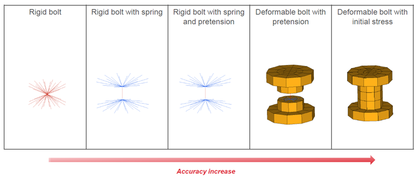
Fig. 1: Bolt modeling methods
Use one rigid body (/RBODY) connected to the parts where the bolt is linked is the simplest method. Although this method is very stable and easy to modeling, but with this method you could not consider pretension, elasto-plastic and rupture behavior for bolt, and there is no force output and model the bolt head passing through the hole is not possible.
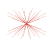
Fig. 2: Rigid bolt modeling method
Note: The master node should be a free node.
Use two rigid bodies (/RBODY) connected to each set of parts which are linked with the bolt and then set one spring element (/PROP/SPR_BEAM) between both rigid bodies. With this method it is possible to describe the elasto-plastic behavior rupture behavior in any direction, and the force passing through the bolt (normal force, shear force, moments) could be output, using /TH/SPRING. This method is often used in the automotive crash analysis, but it has limited capability to model the pretension.
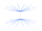
Fig. 3: Rigid bolt with spring
Note:
| 1. | The master node should be a free node. |
| 2. | The spring element is attached to the rigid bodies as slave node. |
To describe pretension with this method another two spring elements (/PROP/SPR_PRE and /PROP/SPR_BEAM) need to be added. /IMPDISP or /CLOAD could be used to simulate preloading. Auto-balance state is calculated by RADIOSS.
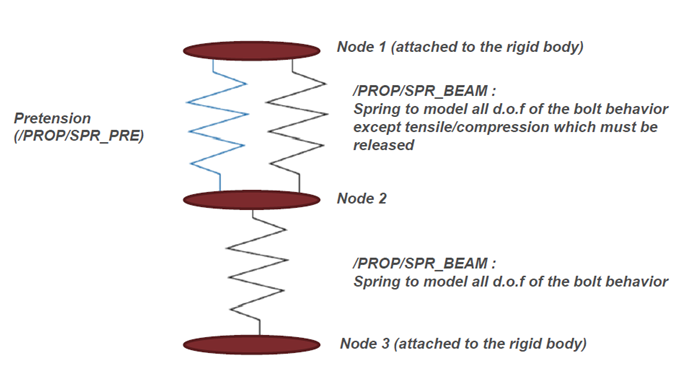
Fig. 3: Modeling pretension with springs
Meshed bolt with solid elements (/BRICK or any other solid element type) and cut in the middle. Two rigid bodies connected to each side of meshed bolt and spring series (two springs with /PROP/SPR_BEAM and one spring with /PROP/SPR_PRE) like above between rigid bodies are used to describe the pretension. With this more detailed model, the bolt head passing through the hole could be considered in simulate.
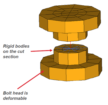
Fig. 4: Deformable bolt with spring and pretension
With this method, bolt is fully-meshed with solid elements (/BRICK), which is more realistic, and the material and failure character could be easily defined. Use /SECT to get section force/moment (/TH/SECT) in bolt. To define the pretension, initial stress (/INIBRI/STRS_F) is needed to get an initial analysis (tensile test on the bolt).
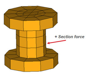
Fig. 5: Fully-meshed deformable bolt
Note:
| 1. | The rupture and stress accuracy depend of the mesh size. |
| 2. | Section force in the bolt is necessary to measure the forces passing through the hole. |
See Also:
RD-3510: Cantilever Beam with Bolt Pretension