There are three different ways for modeling spotweld:
| • | Spring (/PROP/TYPE13) Connect |
Spring (/PROP/TYPE13) Connect and Solid Connect could also model bolt or adhesive connect (glue).
Node Connect
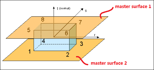
A single interface type 2 with the first surface as master side and some nodes from second surface as slave nodes: With this solution the mesh of the master surface can be independent of the spotweld location. Hourglass problems disappear on the master surface. On the second shell, the surface mesh has to respect the spotweld location and the hourglass problem will remain. The main problem with this modeling approach is the undeformability of the connection and its infinite strength.
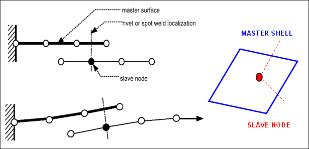
Fig. 4.11: Example of connection between 2 shell surfaces
Spring (/PROP/TYPE13) Connect
Two tied interfaces and a spring: The use of two tied interfaces will provide a full symmetrical solution allowing a free mesh on the two surfaces and avoiding hourglass. The spotweld is modeled with a beam type spring element. The element uses independent nodes not connected on the shell elements. One of the two nodes is located on the first surface (or near, there is no need to be located exactly on the shell surface) and the second node is located on the second surface. One tied interface connects one spring node with the first surface and a second tied interface does the same on the second surface.
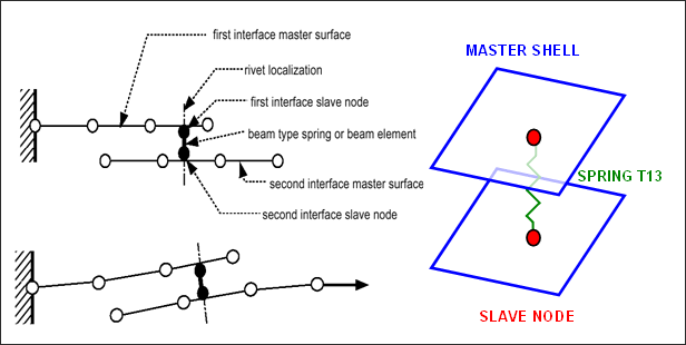
Fig. 4.12: Spotweld modeling
To create a spotweld using this method is a good alternative solution with this approach the connection location is independent from the shell mesh. It is accurate since the spotweld properties are input directly to spring type 13. Below is a basic input for spring type 13 to model spotwelds:
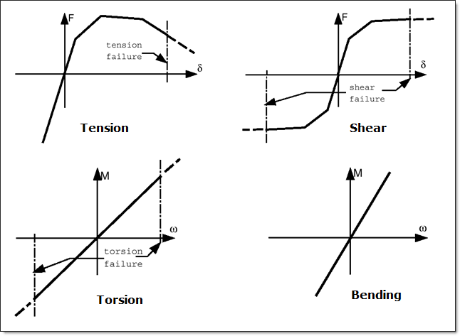
Fig. 4.13: Spring type 13 - typical input for spotweld
Moreover, two different way for modeling rupture of the spotweld.
| 1. | Use failure criteria which available for a spring type 13. More detail see comment of failure criteria in /PROP/TYPE13. |
| 2. | Use Spotflag = 20, 21, or 22 in Tied Contact (/INTER/TYPE2). |
Remark 1: The modeling technique for the spotweld can also be used for other kinds of connections as welding lines, hemming, glue and bolts. For bolt modeling the use of tied interface is not necessary, as the shell nodes can be put directly in the rigid bodies.
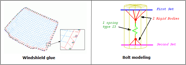
Fig. 4.14: Examples of glue and bolt modeling
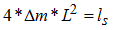
Remark 2: With a tied interface, the slave node mass is transferred to the master nodes. If SPOTflag is set to 1, the slave node inertia is equally distributed over the master nodes by adding mass, so that the induced inertia (at the center of the master surface) is equal to the inertia of the slave node. If the master surface is a perfect square, the added mass is computed as follows:
|
 m: added mass m: added mass
L: distance between the master node and the center
ls: inertia of the slave node
|
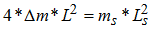
As long as the slave node inertia is realistic, the added mass will be very small. A large added mass is observed if the slave node is a distance from the master surface. The ideal will be for the slave node to lie on the master surface right at the center. If this is not the case, the slave node has inertia at the center of the shell surface:

|
ms: slave node mass
Ls: distance between the slave node and the center
ls: inertia of the slave node
|
Consequently, a new added mass is set to the master nodes, so that the inertia (due to this new added mass) is equal to the inertia, due to the off-centering of the slave node.
If Spotflag =0, there is no added mass, since the slave node inertia is transferred as inertia to the master node. An added inertia that is too large will seriously decrease the accuracy.
Solid Connect
Use 8-node brick element (with /PROP/TYPE43) and /MAT/LAW59+/FAIL/CONNECT (or /MAT/LAW83+/FAIL/SNCONNECT) to modeling solid spotweld, which could provide more accurate results.
| • | The brick element use /PROP/TYPE43 and it has 4 integration point on the shear plane, which is between plane (1, 2, 3, 4) and plane (5, 6, 7, 8). One integration point in normal direction t. This element does not have time step itself and its stability is done by the nodal connection. So the thickness of a spotweld could be very small. This character is very useful for modeling glue. |
| • | INTER/TYPE2 used to connect solid spotweld with two upper and lower master surfaces. |
| • | For this modeling /MAT/LAW59+/FAIL/CONNECT (or /MAT/LAW83+/FAIL/SNCONNECT) could be used for solid spotweld. |
| o | /MAT/LAW59 defines normal stress and shear stress curve (strain rate dependent) to describe the material character. |
| o | With /FAIL/CONNECT elongation criteria and/or energy criteria could be used to describe the failure of spotweld. |
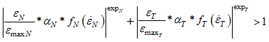
| o | The failure occurs when the normal relative displacement or shear relative displacement is reached according 2 behavior type:
Uncoupled failure (Ifail=0: uni-directional failure)
with i=33 for normal direction and 13 or 23 for tangent directions |
| o | Coupled failure (Ifail=1: multi-directional failure)
 |
The element deletion occurs when one integration point reaches the failure criteria, if Isolid=1, or all integration points reach the failure criteria, if Isolid=2.
| o | Use  and and  in /MAT/LAW83 to fit peel load and mixed-mode load cases (ex: 30° and 60° load) in /MAT/LAW83 to fit peel load and mixed-mode load cases (ex: 30° and 60° load) |
| o | In /FAIL/SNCONNECT defined is plastic elongation vs plastic elongation rate for damage initiation, failure for normal and shear direction. |
See Also:
Example 48 - Solid Spotweld


