|
»Click here to display Table of Contents«
|

CONTPRM |

|

|

|

|
|
CONTPRM |
|
|

|

|
|
»Click here to display Table of Contents«
|
CONTPRM |
|
|
|
|
|
CONTPRM |
|
|
|
|
Bulk Data Entry
CONTPRM – Default Contact Properties
Description
Defines the default properties of all contacts and sets parameters that affect all contacts. The default values set here can be overridden by values explicitly specified on PCONT, PCONTX, and CONTACT cards.
|
Format
(1) |
(2) |
(3) |
(4) |
(5) |
(6) |
(7) |
(8) |
(9) |
(10) |
CONTPRM |
PARAM1 |
VALUE1 |
PARAM2 |
VALUE2 |
PARAM3 |
VALUE3 |
PARAM4 |
VALUE4 |
|
|
PARAM5 |
VALUE5 |
|
|
|
|
|
|
|
|
Field |
Contents |
PARAMi |
Name of parameter. |
VALi |
Value of parameter. |
Parameters for Small Displacement Nonlinear Analysis
Name |
Values |
||||
|---|---|---|---|---|---|
GPAD |
“Padding” of master or slave objects to account for additional layers, such as shell thickness, and so on. This value is subtracted from contact gap opening as calculated from location of nodes. See comment 1. Default = THICK (Real, NONE, or THICK) |
||||
STIFF |
Relative stiffness of the contact interface. See comment 2. Positive value (STIFF = Real > 0.0) is directly specified stiffness. Negative value (STIFF = Real < 0.0) defines a stiffness scaling factor. The stiffness scaling factor is equal to |Real < 0.0|. The scaling is applied to the automatic stiffness value (the stiffness value when STIFF = AUTO). Default = AUTO (AUTO, SOFT, HARD, Real > 0.0, or Real < 0.0) |
||||
MU1 |
Coefficient of static friction (μs). See comments 3 and 4. Default = 0.0 (Real > 0.0 or STICK or FREEZE) |
||||
MU2 |
Coefficient of kinetic friction (μk). Default = MU1 (0.0 < Real < MU1) |
||||
CONTGAP |
Creates a bulk data file that contains internally created node-to-surface contact elements represented as CGAPG elements. The file name is: filename_root.contgap.fem. See comment 5. Default = NO (YES or NO) |
||||
CONTGRID |
Creates a bulk data file that contains SET’s of grids involved with surface-to-surface contact elements. The file name is: filename.root.contgrid.fem. Default = NO (YES or NO) |
||||
CONTOUT |
Creates a bulk data file that contains internal created Surface-to-Surface Contact Elements represented as PLOTEL and RBE3 elements for visualization. The file name is: <filename>.contout.fem. Default = NO (YES or NO) |
||||
CONTMPC |
Outputs internally created MPC’s used to generate TIE contact. The MPC’s are output to: Default = NO (YES or NO) |
||||
TIE |
Indicates the type of contact formulation that is used when the TIE bulk data entry is present in the model. Default = PENALTY (PENALTY or MPC) PENALTY – the default formulation of the TIE contact. MPC – activates the MPC-based formulation of TIE contact. |
||||
CORIENT |
Indicates whether the master orientation field MORIENT on the CONTACT card applies to all surfaces or if it excludes solid elements. Default = ONSHELL (ONSHELL or ONALL) ONSHELL – MORIENT applies only to contact masters that consist of shell elements or patches of grids. Master surfaces defined as faces of solid elements always push outwards, irrespective of initially open or pre-penetrating contact. ONALL – MORIENT applies to all contact masters including, in particular, solid elements. |
||||
SFPRPEN |
Indicates whether initial pre-penetrations are recognized and resolved in self-contact areas. (This only affects self-contact areas, wherein Master and Slave belong to the same set or surface). Default = YES (YES or NO) YES – Initial self-penetrations are recognized and resolved in self-contact areas. There is some danger of finding false self-penetrations across solids thinner than SRCHDIS. Refer to Resolution of Pre-penetration in the User's Guide. NO – There is no pre-penetrations to be resolved in self-contact areas, except maybe minimal intrusions due to meshing, and so on. Any self-penetrations larger than minimum element size will be ignored in those areas. |
||||
FRICESL |
Frictional elastic slip – distance of sliding up to which the frictional transverse force increases linearly with slip distance. Specified in physical distance units (similar to U0 and GPAD). Refer to Friction in the User's Guide.
Default = AUTO (Real > 0.0 or AUTO) |
||||
ADJGRID |
Creates a bulk data file that contains contact grid SET’s. The coordinates of these grids are adjusted (ADJUST), and a bulk data file that contains new coordinates of these contact grids after adjustment is also created. The file names are: filename_root.adjgset.fem and filename_root.adjgcrd.fem. Default = NO (YES or NO) |
||||
DISCRET |
Contact discretization approach for all the CONTACT/TIE entries which do not have an explicit DISCRET specification. Default = N2S (N2S or S2S) |
Parameters for geometric nonlinear analysis (ANALYSIS = EXPDYN in subcase)
Name |
Values |
STFAC |
Interface stiffness scale factor. Default = 1.0 in implicit analysis Default = 0.1 in explicit analysis (Real > 0) |
FRIC |
Coulomb friction. Default = 0.0 (Real > 0) |
GAP |
Gap for impact activation (Comments 7 and 8). (Real > 0) |
IDEL |
Node and segment deletion flag. Default = 0 (Integer = 0, 1, or 2) 0 - No deletion. |
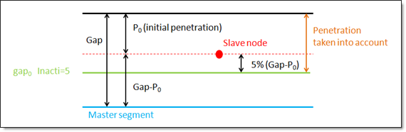
INACTI |
Handling of initial penetrations flag (Comment 10). Default as defined by CONTPRM (Integer = 0, …, 5) 0 - No action. gap0 = gap - P0 – 0.05*(gap - P0) Valid in explicit analysis: 0, 1, 2, 3 and 5. Valid in implicit analysis: 0, 3 and 4. Invalid entries are ignored. |
CORIENT |
Indicates whether the master orientation field MORIENT on the CONTACT card applies to all surfaces, or if it excludes solid elements. Default = ONSHELL (ONSHELL or ONALL) ONSHELL – MORIENT applies only to contact masters that consist of shell elements or patches of grids. Master surfaces defined as faces of solid elements always push outwards, irrespective of initially open or pre-penetrating contact. ONALL – MORIENT applies to all contact masters including, in particular, solid elements. |
IFRIC |
Friction formulation flag (Comment 12). Default = COUL (Character = COUL, GEN, DARM, or REN) COUL - Static Coulomb friction law. In implicit computation, only IFRIC = COUL is implemented. |
IFILT |
Friction filtering flag (Comment 11). Default = NO (Character = NO, SIMP, PER, or CUTF) NO - No filter is used. |
FFAC |
Filtering coefficient (Only with IFILT ≠ NO). (0.0 < Real < 1.0) |
IFORM |
Type of friction penalty formulation (Comments 13 and 14). Default = VISC (Character = VISC or STIFF) VISC - Viscous (total) formulation. |
C1, C2, C3, C4, C5, C6 |
Friction law coefficients. (Real > 0) |
IGNORE |
Flag to ignore slave nodes if no master segment is found for TIE contact (Comment 15). Default = 1 (Integer = 0, 1, or 2) 0 - No deletion of slave nodes; 1 - Slave nodes with no master segment found are deleted from the interface; 2 - Slave nodes with no master segment found are deleted from the interface; if SRCHDIS is blank, then it would be newly calculated internally. |
MTET10 |
Flag for second order CTETRA as contact master surface. Default = 0 (Integer = 0 or 1) 0 - TETRA 10 is degenerated on the surface (middle nodes are removed from contact); 1 - Four triangular segments are used on each tetra face. |
The following entries are relevant for explicit analysis only. |
|
ISYM |
Symmetric contact flag. Default = SYM (Character = SYM or UNSYM) SYM – Symmetric contact. UNSYM – Master-slave contact. If SSID defines a grid set, the contact is always a master-slave contact. |
IEDGE |
Flag for edge generation from slave and master surfaces. Default = NO (Character = NO, ALL, BORD, or FEAT) NO – No edge generation. ALL – All segment edges are included. BORD – External border of slave and master surface is used. FEAT – External border as well as features defined by FANG are used. |
FANG |
Feature angle for edge generation in degrees (Only with IEDGE = FEAT). Default = 91.0 (Real > 0) |
IGAP |
Gap definition flag. Default = CONST (Character = CONST or VAR) CONST - Gap is constant and equal to GAP (Comments 8 and 9). VAR - Gap is variable (in space, not in time) according to the characteristics of the impacting surfaces and nodes (See comment 9). |
ISTF |
Stiffness definition flag (Comment 6). Default = 0 (Integer = 0, …, 5) 0 - The stiffness is computed according to the master side characteristics. 1 - STIF1 is used as interface stiffness. 2, 3, 4 and 5 - The interface stiffness is computed from both master and slave characteristics. |
STIF1 |
Interface stiffness (Only with ISTF = 1). Default = 0.0 (Real > 0) |
STMIN |
Minimum interface stiffness (Only with ISTF > 1). (Real > 0) |
STMAX |
Maximum interface stiffness (Only with ISTF > 1). Default = 1030 (Real > 0) |
IBC |
Flag for deactivation of boundary conditions at impact. (Character = X, Y, Z, XY, XZ, YZ, or XYZ) |
VISS |
Critical damping coefficient on interface stiffness. Default = 0.05 (Real > 0) |
VISF |
Critical damping coefficient on interface friction. Default = 1.0 (Real > 0) |
BMULT |
Sorting factor. Default = 0.20 (Real > 0) |
Comments for quasi-static analysis
| 1. | The initial gap opening is calculated automatically based on the relative location of slave and master nodes (in the original, undeformed mesh). To account for additional material layers covering master or slave objects (such as half of shell thickness), the GPAD entry can be used. GPAD option THICK automatically accounts for shell thickness on both sides of the contact interface (this also includes the effects of shell element offset ZOFFS or composite offset Z0). |
| 2. | Option STIFF=AUTO determines the value of normal stiffness for each contact element using the stiffness of surrounding elements. Additional options SOFT and HARD create respectively softer or harder penalties. SOFT can be used in cases of convergence difficulties and HARD can be used if undesirable penetration is detected in the solution. A negative value for STIFF indicates that a stiffness scaling factor equal to |Real < 0.0| is defined. This scaling is applied on the stiffness value via STIFF = AUTO. |
| 3. | MU1=STICK is interpreted in OptiStruct as an enforced stick condition - such contact interfaces will not enter the sliding phase. Of course, the enforced stick only applies to contacts that are closed. |
| 4. | MU1=FREEZE enforces zero relative displacements on the contact surface – the contact gap opening remains fixed at the original value and the sliding distance is zero. The FREEZE condition applies to all slave nodes, no matter whether their initial gap is open or closed. |
| 5. | The file filename_root.contgap.fem, produced using the CONTGAP parameter, can be imported into HyperMesh in order to visualize internally created node-to-surface contact elements (now converted to GAPG entities). Note that during optimization, this file shows node-to-surface contact elements for the latest optimization iteration. In order to correctly visualize this configuration in HyperMesh for shape optimization problems, the FEA mesh shape needs to be updated by applying "Shape change" results. |
Furthermore, if GAPPRM,HMGAPST,YES is activated together with CONTPRM,CONTGAP,YES, then the gap status command file, filename_root.HM.gapstat.cmf, will also include the open/closed status of these additional GAPG’s that represent node-to-surface contact elements. For correct visualization of their status in HyperMesh, file filename_root.contgap.fem needs to be imported before running the gap status command file.
Comments for geometric nonlinear analysis (ANALYSIS = EXPDYN in subcase)
| 6. | If ISTF ≠ 1, the interface stiffness K is computed from the master segment stiffness Km and/or the slave segment stiffness Ks. |
The master stiffness is computed from Km = STFAC * B * S * S/V for solids, Km = 0.5 * STFAC * E * t for shells as well as when the master segment is shared by a shell and a solid.
The slave stiffness is an equivalent nodal stiffness computed as Ks = STFAC * B * V-3 for solids, Ks = 0.5 * STFAC * E * t for shells.
In these equations, B is the Bulk Modulus, S is the segment area, E is the modulus of elasticity, t is shell thickness, and V is the volume of a solid. There is no limitation to the value of stiffness factor (but a value greater than 1.0 can reduce the initial time step).
ISTF = 0, the interface stiffness K = Km
ISTF > 1, the interface stiffness is K = max (STMIN, min (STMAX, K1)) with
| • | ISTF = 2, K1 = 0.5 * (Km + Ks) |
| • | ISTF = 3, K1 = max (Km, Ks) |
| • | ISTF = 4, K1 = min (Km, Ks) |
| • | ISTF = 5, K1 = Km * Ks / (Km + Ks) |
| 7. | In an implicit analysis, the contact stiffness plays a very important role in convergence. ISTF = 4 (which takes the minimum of master and slave stiffness’s for contact) is recommended. This is because the penalty contact force will be balanced with the internal force of the deformable impacted part, which means the stiffness near the effective stiffness one will converge easier than a higher one. |
For small initial gaps in implicit analysis, the convergence will be more stable if a GAP larger than the initial gap is defined.
In implicit analysis, sometimes a stiffness with scaling factor reduction (for example: STFAC = 0.01) or reduction in impacted thickness (if rigid one) might reduce unbalanced forces and improve convergence, particularly in shell structures under bending where the effective stiffness is much lower than membrane stiffness; but it should be noted that too low of a value could also lead to divergence.
| 8. | The default for the constant gap (IGAP = CONST) is the minimum of |
| • | t, average thickness of the master shell elements |
| • | l/10, l – average side length of the master solid elements |
| • | lmin/2, lmin – smallest side length of all master segments (shell or solid) |
| 9. | The variable gap (IGAP = VAR) is computed as gs + gm |
with:
| • | gm - master element gap with |
gm = t/2, t: thickness of the master element for shell elements.
gm = 0 for solid elements.
| • | gs - slave node gap: |
gs = 0 if the slave node is not connected to any element or is only connected to solid or spring elements.
gs = t/2, t - largest thickness of the shell elements connected to the slave node.
gs = 1/2√S for truss and beam elements, with S being the cross-section of the element.
If the slave node is connected to multiple shells and/or beams or trusses, the largest computed slave gap is used.
The variable gap is always at least equal to GAPMIN.
| 10. | INACTI = 3 or 4 are only recommended for small initial penetrations and should be used with caution because: |
| • | the coordinate change is irreversible |
| • | it may create other initial penetrations if several surface layers are defined in the interfaces |
| • | it may create initial energy if the node belongs to a spring element |
INACTI = 5 works as follows:
| 11. | IFILT defines the method for computing the friction filtering coefficient. If IFILT ≠ NO, the tangential friction forces are smoothed using a filter: |
FT = α * F'T + (1 - α) * F'T-1
Where,
FT is the tangential force
F'T is the tangential force at time t
F'T-1 is the tangential force at time t-1
α is the filtering coefficient
IFILT = SIMP – α = FFAC
IFILT = PER – α = 2![]() dt/FFAC, where dt/T = FFAC, T is the filtering period
dt/FFAC, where dt/T = FFAC, T is the filtering period
IFILT = CUTF – α = 2![]() * FFAC * dt, where FFAC is the cutting frequency
* FFAC * dt, where FFAC is the cutting frequency
| 12. | IFRIC defines the friction model. |
IFRIC = COUL – Coulomb friction with FT < μ * FN with μ = FRIC
If IFRIC is not COUL, the friction coefficient is set by a function (μ = μ(p, V)), where p is the pressure of the normal force on the master segment and V is the tangential velocity of the slave node.
The following formulations are available:
IFRIC = GEN - Generalized viscous friction law
μ = Fric + C1 * p + C2 * V + C3 * p * V + C4 * p2 + C5 * V2
IFRIC = DARM - Darmstad law
μ = C1 • e(C2V) • p2 + C3 • e(C4V) • p + C5 • e(C6V)
IFRIC = REN - Renard law
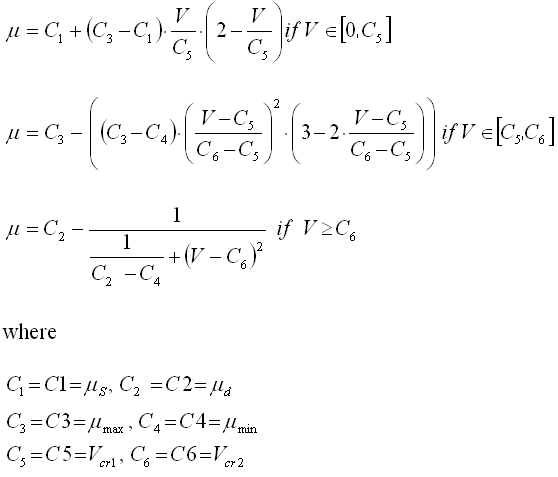
| • | The first critical velocity Vcr1 must be different to 0 (C5 ≠ 0). It also must be lower than the second critical velocity Vcr2 (C5 < C6). |
| • | The static friction coefficient C1 and the dynamic friction coefficient C2 must be lower than the maximum friction C3 (C1 < C3) and C2 < C3). |
| • | The minimum friction coefficient C4, must be lower than the static friction coefficient C1 and the dynamic friction coefficient C2 (C4 < C1 and C4 < C2). |
| 13. | IFORM selects two types of contact friction penalty formulation. |
The viscous (total) formulation (IFORM = VISC) computes an adhesive force as
Fadh = VISF * Sqrt(2Km) * VTFT = min (μFN, Fadh)
The stiffness (incremental) formulation (IFORM = STIFF) computes an adhesive force as
Fadh = FTold + ΔFT
ΔFT = K * VT * dt
FTnew = min (μFN, Fadh)
| 14. | For nonlinear implicit contact with friction, the stiffness formulation (IFORM = STIFF) is recommended. |
| 15. | If IGNORE = 1 or 2, the slave nodes without a master segment found during the searching are deleted from the interface. |
If IGNORE = 1 and SRCHDIS is blank, the default value of the distance for searching closest master segment is the average size of the master segments.
If IGNORE = 2 and SRCHDIS is blank, the distance for searching closest master segment is computed as follows for each slave node:
d1 = 0.6 * (Ts + Tm)
d2 = 0.05 * Tmd
SRCHDIS = max(d1, d2 )
Where,
Ts is the thickness of the element connected to the slave node, for solids Ts = 0.0
Tm is the thickness of master segment, for solids Tm = Element volume / Segment area
Tmd is the master segment diagonal
| 16. | This card is represented as a control card in HyperMesh. |
See Also:
Geometric Nonlinear Analysis