|
»Click here to display Table of Contents«
|

CPENTA |

|

|

|

|
|
CPENTA |
|
|

|

|
|
»Click here to display Table of Contents«
|
CPENTA |
|
|
|
|
|
CPENTA |
|
|
|
|
Bulk Data Entry
CPENTA – Five-sided Solid Element with six or fifteen grid points
Description
Defines the connections of the CPENTA element.
Format
(1) |
(2) |
(3) |
(4) |
(5) |
(6) |
(7) |
(8) |
(9) |
(10) |
CPENTA |
EID |
PID |
G1 |
G2 |
G3 |
G4 |
G5 |
G6 |
|
|
G7 |
G8 |
G9 |
G10 |
G11 |
G12 |
G13 |
G14 |
|
|
G15 |
|
|
|
|
|
|
|
|
|
CORDM |
CID |
|
|
|
|
|
|
|
|
Field |
Contents |
EID |
Unique element identification number. No default (Integer > 0) |
PID |
A PSOLID property entry identification number. Default = EID (Integer > 0) |
G# |
Connected grid points identification number. Default = blank (Integer > 0 or blank) |
CORDM |
Flag indicating that the following field references the material coordinate system. |
CID |
Identification number of the material coordinate system. Default = 0 (Integer ≥ -1) |
| 1. | The topology of the diagram must be preserved, that is, G1, G2, and G3 define a triangular face, G1-G4, G2-G5, and G3-G6 each form one edge. |
The edge points, G7-G15, are optional. If any of the edge points are present, they all must be used. The second and third continuation is not needed for the six node version of this element.
It is recommended that the edge points be placed near the middle of the edge.
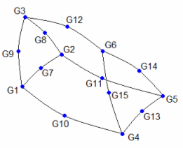
CPENTA definition
| 2. | If the user-defined node numbering on the bottom and top faces is reversed as compared to the sequence shown above, the nodes are renumbered to produce right-handed orientation of numbering. This is accomplished by swapping nodes G1 with G3 and G4 with G6. For 15-noded CPENTA, appropriate changes to mid-side node numbering are also performed. In such cases, the element coordinate system will be built on the renumbered node sequence. |
| 3. | Stresses are output in the material coordinate system. The material coordinate system is defined on the referenced PSOLID entry. It may be defined as the basic coordinate system (CORDM = 0), a defined system (CORDM = Integer > 0), or the element coordinate system (CORDM = -1). |
| 4. | The element coordinate system for the CPENTA element is defined as follows: |
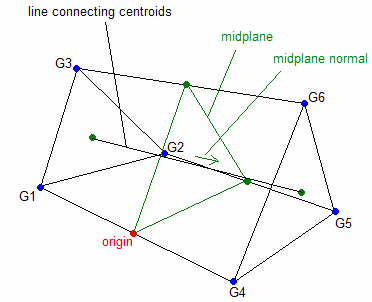
CPENTA element coordinate system
The origin of the element coordinate system is located at the mid-point of a straight line from G1 to G4.
The element z-axis corresponds to the average of the vector connecting the centroid of triangular face G1-G2-G3 to the centroid of the triangular face G4-G5-G6 and the normal vector of the mid-plane (the plane on which the mid-points of the straight lines G1-G4, G2-G5, and G3-G6 lie). The positive sense of the z-axis is toward the triangular face G4-G5-G6.
The element y-axis is perpendicular to the element z-axis and lies on the plane created by the element z-axis and the line connecting the origin and the mid-point of a straight line from G3 to G6. The positive sense of the y-axis is toward the straight line from G3 to G6.
The element x-axis is the cross product of the element y-axis and the element z-axis.
| 5. | This card is represented as a penta6 or penta15 element in HyperMesh. |
See Also: