|
»Click here to display Table of Contents«
|

CPYRA |

|

|

|

|
|
CPYRA |
|
|

|

|
|
»Click here to display Table of Contents«
|
CPYRA |
|
|
|
|
|
CPYRA |
|
|
|
|
Bulk Data Entry
CPYRA – Five-sided Solid Element with five or thirteen grid points
Description
Defines the connections of the PYRA solid element.
Format
(1) |
(2) |
(3) |
(4) |
(5) |
(6) |
(7) |
(8) |
(9) |
(10) |
CPYRA |
EID |
PID |
G1 |
G2 |
G3 |
G4 |
G5 |
G6 |
|
|
G7 |
G8 |
G9 |
G10 |
G11 |
G12 |
G13 |
|
|
|
CORDM |
CID |
|
|
|
|
|
|
|
|
Field |
Contents |
EID |
Unique element identification number. No default (Integer > 0) |
PID |
A PSOLID property entry identification number. Default = EID (Integer > 0) |
G# |
Grid point identification numbers of connection points. Default = blank (Integer > 0 or blank) |
CORDM |
Flag indicating that the following field references the material coordinate system. |
CID |
Identification number of the material coordinate system. Default = 0 (Integer ≥ -1) |
| 1. | Grid points G1,…,G4 must be given in consecutive order about the quadrilateral face. |
The edge points, G6 through G13, are optional. If any of the edge points are present, they all must be used. The continuation must not be present for the 5-noded version of this element.
It is recommended that the edge points be placed near the middle of the edge.
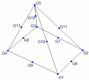
CPYRA definition
| 2. | Stresses are output in the material coordinate system. The material coordinate system is defined on the referenced PSOLID entry. It may be defined as the basic coordinate system (CORDM = 0), a defined system (CORDM = Integer > 0), or the element coordinate system (CORDM = -1). |
| 3. | The element coordinate system for the CPYRA element is defined as follows: |
Three intermediate vectors R, S, and T are chosen by the following rules:
R |
Joins the midpoints of the edges from G1 to G4 and G2 to G3. |
S |
Joins the midpoints of the edges from G1 to G2 and G3 to G4. |
T |
Joins the intersection of R and S to G5. |
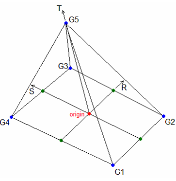
CPYRA element coordinate system
The origin of the element coordinate system is located at the intersection of the vectors R and S.
The element z-axis corresponds to the T vector.
The element y-axis is the cross product of the T and R vectors.
The element x-axis is the cross product of the element y-axis and the element z-axis.
| 4. | This card is represented as a pyra5 or pyra13 element in HyperMesh. |
See Also: