|
»Click here to display Table of Contents«
|

CQUAD4 |

|

|

|

|
|
CQUAD4 |
|
|

|

|
|
»Click here to display Table of Contents«
|
CQUAD4 |
|
|
|
|
|
CQUAD4 |
|
|
|
|
Bulk Data Entry
CQUAD4 – Quadrilateral Element Connection
Description
Defines a quadrilateral plate element (QUAD4) of the structural model. This element uses a 6 degree-of-freedom per node formulation.
Format
(1) |
(2) |
(3) |
(4) |
(5) |
(6) |
(7) |
(8) |
(9) |
(10) |
CQUAD4 |
EID |
PID |
G1 |
G2 |
G3 |
G4 |
Theta |
ZOFFS |
|
|
|
|
T1 |
T2 |
T3 |
T4 |
|
|
|
|
Field |
Contents |
EID |
Unique element identification number. No default (Integer > 0) |
PID |
Identification number of a PSHELL, PCOMP, PCOMPP or PHFSHL property entry. Default = EID (Integer > 0) |
G1,G2,G3,G4 |
Grid point identification numbers of connection points. No default (Integers > 0, all unique) |
Theta |
Material orientation angle in degrees. Default = 0.0 (Real) |
MCID |
Material coordinate system identification number. The x-axis of this coordinate system is projected onto the element to define the x-axis of the material coordinate system. If MCID = 0, it specifies the basic coordinate system. MCID must be an integer > 0. If blank, Theta = 0.0 is used. See comments 3 through 5. Default is Theta = 0.0 (Integer > 0) |
ZOFFS |
Offset from the plane defined by element grid points to the shell reference plane. See comment 10. Overrides the ZOFFS specified on the PSHELL entry. Default = 0.0 (Real, Character Input = TOP/BOTTOM, or blank) |
Ti |
Thickness of the element at the grid points. Overrides the thickness specified on the PSHELL entry. If Ti is specified, the average of all four thicknesses is used as the element thickness. For defaults: See comments 6 and 8. (Real > 0.0 or blank) |
| 1. | Grid points G1 through G4 must be ordered consecutively around the perimeter of the element. |
| 2. | All of the interior angles must be less than 180 degrees. |
| 3. | The elemental coordinate system is a bisection definition as depicted in the following figure: |
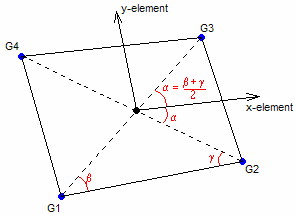
Elemental coordinate system
| 4. | For H3D and OUTPUT2 output formats, stresses and strains are always output in the elemental system. |
| 5. | For HM, PUNCH and OPTI output formats, stresses and strains are output by default in the material coordinate system. PARAM, OMID can be set to NO to output results in the elemental system. For elements with blank Theta/MCID, THETA = 0.0 is assumed, and the material coordinate system is aligned with side G1-G2 of the shell element. For elements with assigned THETA, the material x-axis is rotated from side G1-G2 by angle THETA. For elements with MCID, the material system is constructed by projecting the MCID onto the plane of the element. |
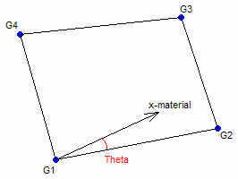
Orientation when Theta (real value) is entered in 8th field
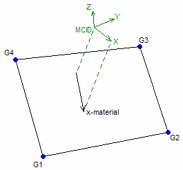
Orientation when MCID (integer value) is entered in 8th field
| 6. | If any of the Ti fields are blank, the thickness specified on the PSHELL data will be used for that node’s thickness. If 0.0 is specified for Ti, then the thickness at that node is zero. |
| 7. | If the property referenced by PID is selected as a region for free-size or size optimization, then any Ti values defined here are ignored. If you input Ti for elements in the design space for Topology or Free-Size optimization, the run will error out. |
| 8. | If Ti is present, the PID cannot reference PCOMP or PCOMPP data. |
| 9. | The shell reference plane can be offset from the plane defined by element nodes by means of ZOFFS. In this case all other information, such as material matrices or fiber locations for the calculation of stresses, is given relative to the offset reference plane. Similarly, shell results, such as shell element forces, are output on the offset reference plane. |
ZOFFS can be input in two different formats:
| 1. | Real: |
A positive or a negative value of ZOFFS is specified in this format. A positive value of ZOFFS implies that the reference plane of each shell element is offset a distance of ZOFFS along the positive z-axis of its element coordinate system.
| 2. | Surface: |
This format allows you to select either “Top” or “Bottom” option to specify the offset value.
Top:
The top surface of the shell element and the plane defined by the element nodes are coincident.
This makes the effective "Real" ZOFFS value equal to half of the thickness of the PSHELL property entry referenced by this element. (The sign of the ZOFFS value would depend on the direction of the offset relative to the positive z-axis of the element coordinate system, as defined in the Real section). See Figure 1.
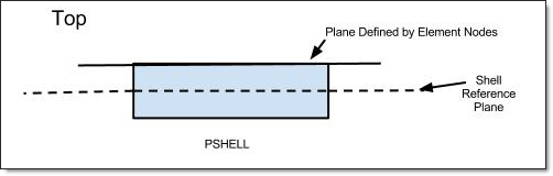
Figure 1: Top option in ZOFFS
Bottom:
The bottom surface of the shell element and the plane defined by the element nodes are coincident.
This makes the effective "Real" ZOFFS value equal to half of the thickness of the PSHELL property entry referenced by this element. (The sign of the ZOFFS value would depend on the direction of the offset relative to the positive z-axis of the element coordinate system, as defined in the Real section). See Figure 2.
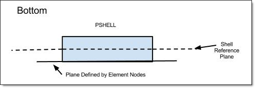
Figure 2: Bottom option in ZOFFS
Note that when ZOFFS is used, both MID1 and MID2 must be specified on the PSHELL entry referenced by this element (otherwise, singular matrices would result).
Offset is applied to all element matrices (stiffness, mass, and geometric stiffness), and to respective element loads (such as gravity). Hence, ZOFFS can be used in all types of analysis and optimization. Note, however, that for first order shell elements (CQUAD4 and CTRIA3), the offset operation does not correct for secondary effects, such as change of shell area when offset is applied on curved surfaces. Therefore, the value of ZOFFS should be kept within a reasonable percentage (10% - 15%) of the local radius of curvature. Automatic offset control is available in composite free-size and sizing optimization where the specified offset values are automatically updated based on thickness changes.
Moreover, while offset is correctly applied in geometric stiffness matrix and hence can be used in linear buckling analysis, caution is advised in interpreting the results. Without offset, a typical simple structure will bifurcate and loose stability “instantly” at the critical load. With offset, though, the loss of stability is gradual and asymptotically reaches a limit load, as shown below in figure (b):
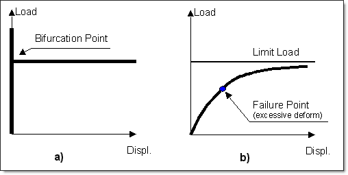
Therefore, the structure with offset can reach excessive deformation before the limit load is reached. The above illustrations apply to linear buckling – in a fully nonlinear limit load simulation, additional instability points may be present on the load path.
| 10. | PHFSHL properties are only valid with an @HYPERFORM statement in the first line of the input file. |
| 11. | The CQUAD4 element utilizes 5 integration points. The reason for utilizing more than 4 integration points is due to the usage of bubble shape functions, which increases the order of approximation beyond that of a standard linear shell. Their actual locations and weights are adjusted based on the element configuration. |
| 12. | This card is represented as a quad4 element in HyperMesh. |
See Also: