|
»Click here to display Table of Contents«
|

PSHELL |

|

|

|

|
|
PSHELL |
|
|

|

|
|
»Click here to display Table of Contents«
|
PSHELL |
|
|
|
|
|
PSHELL |
|
|
|
|
Bulk Data Entry
PSHELL – Shell Element Property
Description
Defines the membrane, bending, transverse shear, and membrane-bending coupling of shell elements.
Format
(1) |
(2) |
(3) |
(4) |
(5) |
(6) |
(7) |
(8) |
(9) |
(10) |
PSHELL |
PID |
MID1 |
T |
MID2 |
12I/T3 |
MID3 |
TS/T |
NSM |
|
|
Z1 |
Z2 |
MID4 |
T0 |
ZOFFS |
|
|
|
|
|
Field |
Contents |
PID |
Unique shell element property identification number. (Integer > 0) |
MID1 |
Material identification number for membrane. See comment 3. (Integer > 0) |
T |
Default value for the membrane thickness (Real > 0.0). If T0 is defined for topology optimization, T is the total thickness. |
MID2 |
Material identification number for bending. See comment 3. (Integer > -1 or blank) |
12I/T3 |
Bending stiffness parameter. See Comment 16. Default = 1.0 (Real > 0.0 or blank) |
MID3 |
Material identification number for transverse shear. See comment 3. (Integer > 0 or blank, must be blank unless MID2 > 0) |
TS/T |
Transverse shear thickness divided by the membrane thickness. Default = .833333 (Real > 0.0 or blank) |
NSM |
Nonstructural mass per unit area. (Real) |
Z1, Z2 |
Fiber distances for stress computation. The positive direction is determined by the right hand rule and the order in which the grid points are listed on the connection entry. (Real or blank, See comment 7 for defaults) |
MID4 |
Material identification number for membrane-bending coupling. (Integer > 0 or blank, must be blank unless MID1 > 0 and MID2 > 0, may not be equal to MID1 or MID2). See comments 10 and 11. |
T0 |
The base thickness of the elements in topology and free-size optimization. Only for MAT1, T0 can be >0.0. If T0 is blank, the elements are not included in the topology design volume or space. (This is a legacy field, use T0 field on DTPL and DSIZE Bulk Data Entries instead to set the corresponding base thickness). (Real > 0.0 or blank for MAT1, Real = 0.0 or blank for MAT2, MAT8) |
ZOFFS |
Offset from the plane defined by element grid points to the shell reference plane. Real or Character Input (Top/Bottom). See comment 14. |
| 1. | The structural mass is computed from the density using the membrane thickness and membrane material properties. |
| 2. | MID1 cannot be left blank. The effect of leaving an MID2 or MID3 field blank is: |
MID2 |
Pure membrane in plane stress – no bending, coupling, or transverse shear stiffness. MID3 and MID4 must also be blank (see comment 15). |
MID3 |
No transverse shear deformation is considered (this is actually accomplished by enforcing very high transverse shear stiffness). |
If MID2 = -1 |
Plane strain. In-plane stiffness only. No bending or transverse shear stiffness. See comments 12, 13 and 15. |
| 3. | The continuation is not required. |
| 6. | The default for Z1 is -T/2, and for Z2 it is +T/2. T is the local plate thickness, defined by T on this entry. For free-sizing optimization, Z1 and Z2 definitions are ignored and the defaults of –T/2 and +T/2 are used for each element. |
| 7. | If MID3 references a MAT2 material, then G33 on the MAT2 data must be blank. |
| 8. | If MID3 references a MAT8 material, then G1Z and G2Z must not be blank. |
| 9. | MID4 provides a way to represent shells with offset (shell element centerline being offset from the plane of the grid points) or shells with material properties that are not symmetric with respect to the middle surface of the shell. However, whenever possible, the preferred method of representing such shells is through the use of element offset ZOFFS or the composite property PCOMP. This is because MID4 does not provide sufficient information about the shell structure to correctly calculate all respective results, specifically: |
| • | The shell stresses calculated in the presence of MID4 are generally incorrect, as they do not reflect the actual shell offset or the non-uniform material structure. |
| • | The effects of MID4 are not considered in the calculation of differential stiffness. Hence, it is recommended that MID4 be left blank in buckling analysis. |
| 10. | If MID4 points to a MAT2 card with a material ID greater than 400,000,000, then the thermal membrane-bending coefficients A1, A2, and A12 have a modified interpretation, and represent [G]*[alpha] rather then [alpha]. Here, [G] is a matrix composed of G11, G22, …, G33. This is to maintain consistency with respective terms generated internally by the PCOMP card. |
| 11. | Thermal expansion coefficients provided for materials referenced as MID2 or MID3 are ignored in shell analysis - only the thermal expansion terms for materials referenced as MID1 (membrane) and MID4 (coupling) are considered. Furthermore, the reference temperature (TREF) for the shell property is taken from the material referenced as MID1 - TREF's provided for other MID's are ignored. |
| 12. | Plane strain (MID2=-1) MID1 must reference a MAT1 entry. |
| 13. | In plane strain computations, in-plane loads are interpreted as line loads with a value equal to the load, divided by the thickness. Thus, if a thickness of "1.0" is used, the value of the line-load equals the load value. Pressure can be approximated with multiple line loads where the pressure value equals the line-load, divided by the length between the loads. |
| 14. | The shell reference plane can be offset from the plane defined by the element nodes by means of ZOFFS. In this case all other information, such as material matrices or fiber locations for the calculation of stresses, is given relative to the offset reference plane. Shell results, such as shell element forces, are output on the offset reference plane. ZOFFS can be used in all types of analysis and optimization. |
ZOFFS can be input in two different formats:
| 1. | Real: |
A positive or a negative value of ZOFFS is specified in this format. A positive value of ZOFFS implies that the reference plane of each shell element is offset a distance of ZOFFS along the positive z-axis of its element coordinate system.
| 2. | Surface: |
This format allows you to select either “Top” or “Bottom” option to specify the offset value.
Top:
The top surface of the shell element and the plane defined by the element nodes are coplanar.
This makes the effective "Real" ZOFFS value equal to half of the thickness of the PSHELL element. (The sign of the ZOFFS value would depend on the direction of the offset with respect to the positive z-axis of the element coordinate system, as defined in the Real section). See Figure 1.
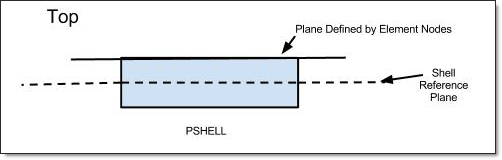
Figure 1: Top option in ZOFFS
Bottom:
The bottom surface of the shell element and the plane defined by the element nodes are coplanar.
This makes the effective "Real" ZOFFS value equal to half of the thickness of the PSHELL element. (The sign of the ZOFFS value would depend on the direction of the offset with respect to the positive z-axis of the element coordinate system, as defined in the Real section). See Figure 2.
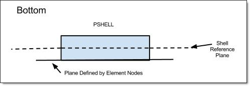
Figure 2: Bottom option in ZOFFS
When ZOFFS is used, both MID1 and MID2 must be specified; otherwise singular matrices would result.
Moreover, while offset is correctly applied in geometric stiffness matrix and thus can be used in linear buckling analysis, caution is advised in interpreting the results. Without offset, a typical simple structure will bifurcate and loose stability “instantly” at the critical load, shown in Figure (a). With offset though, the loss of stability is gradual and asymptotically reaches a limit load, as shown below in Figure (b).
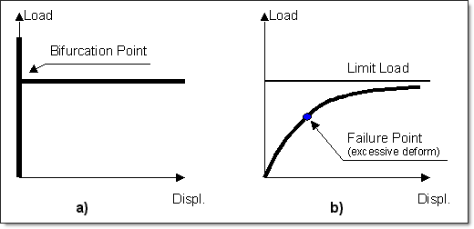
Thus, the structure with offset can reach excessive deformation before the limit load is reached. Note that the above illustrations apply to linear buckling – in a fully nonlinear limit load simulation, additional instability points may be present on the load path.
| 15. | The pure membrane element (in both plane stress and plane strain configurations) does not support bending. Therefore, it is susceptible to large deformation, if the direction normal to the shell is not supported. On ideally flat configurations with no out-of-plane loads, such a large deformation may be avoided without additional support. However, it is recommended to provide support in the normal direction (if the membrane shell is “skinned” on solid surfaces, then this condition is satisfied). |
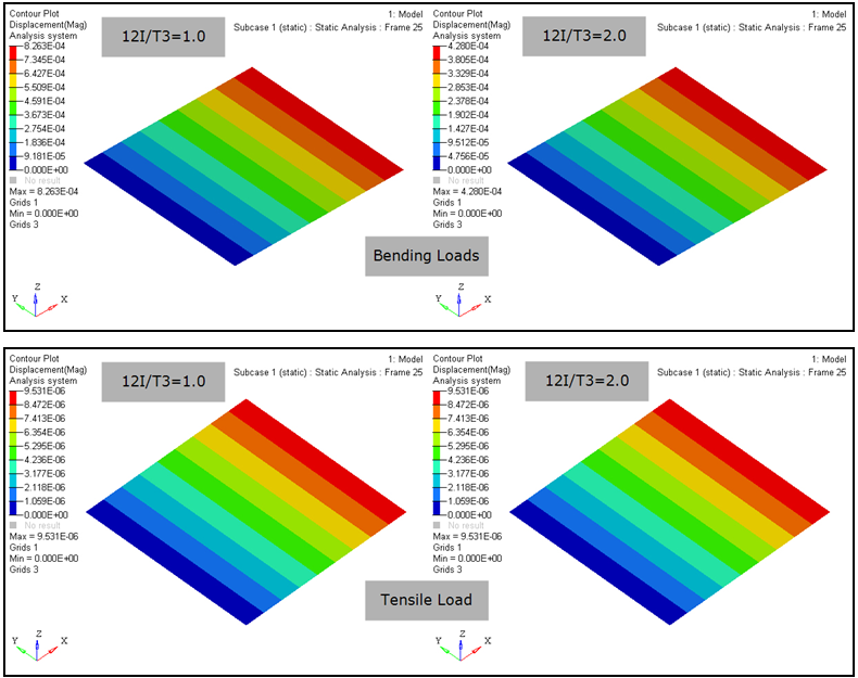
| 16. | The bending stiffness parameter (12I/T3) can be defined as the ratio of the bending moment of inertia of the shell (I) and the bending moment of inertia of a homogeneous shell (T3/12). This parameter influences only the bending stiffness of the shell element (for example, the displacement results due to bending and tensile loads are presented below). The bending stiffness increases with increasing value of 12I/T3. This parameter can be used to represent non-homogeneous material (such as honeycomb, concrete, and so on). |
| 17. | This card is represented as a property in HyperMesh. |
See Also: