In the course of a finite element solution, matrix representations of a structure's stiffness, mass, damping, and loading are generated. The matrices are based on the information provided in the Bulk Data section of the input file. Depending on the analysis type, system equations using these matrices are solved to simulate the structure’s behavior. This is referred to as Direct Matrix Input or Superelements. For ease of use, this section utilizes Superelements to represent such data.
In a linear static analysis, for example, a system of linear equations is solved. Here Ku=f is solved. Where, K is the stiffness matrix, f is the loading vector, and u is the vector of the unknown displacements.
The time taken for these matrix solutions is generally proportional to the square of the number of degrees-of-freedom of the structure. The solution speed can be improved by representing sections of the structure (superelement assemblies) with a smaller subset of degrees of freedom of those sections (boundary degrees of freedom of the superelement assemblies) and a representative set of reduced matrices. In an optimization run, for example, the solution speed can be improved dramatically by removing the non-design portion of the structure and retaining only the design portion of the model.
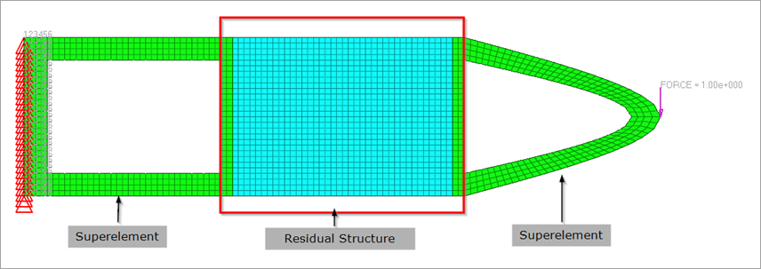
Figure 1: Selecting the Superelements and the Residual Structure.
Solving models using superelements is different from the way you run other models in OptiStruct. Therefore, it is beneficial to initially understand a couple of basic terms typically utilized in these solutions.
Direct Matrix Input/Superelement
A superelement is a reduced representation of the behavior and performance of a structure or a part of a structure.
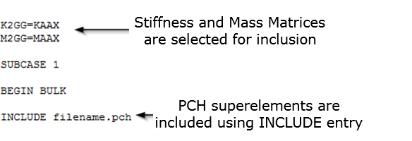
DMIG is the acronym for Direct Matrix Input at Grid points. This matrix is defined by a single header entry and one or more column entries. The DMIG Bulk Data Entry can be used to directly define matrices to be included in the model (such as stiffness and mass matrices). DMIG entries can be selected in the case control section using K2GG, M2GG, B2GG entries and so on for inclusion in the model.
Residual structure
The part of the full model that remains after the superelement has been created is the Residual structure (or simply, Residual).
The reduced loading, mass, stiffness, and damping matrices can be generated using multiple methods illustrated in subsequent sections. Nevertheless, the basic process involved in using superelements to solve a model can be explained as follows:
Superelement Generation Run
The full-model is carefully examined to determine the sections or parts that can be reduced out as superelements. The boundaries between the superelements and the residual structure are identified using connection/interface points (ASET/BNDFIX/BNDFREE and so on). A variety of factors are involved in the decision to make certain sections of the model into superelements, like computations speedup, sparsity or density of the reduced matrices, type of superelement reduction method, and the type of solution (for example, static vs dynamic). Considerable speedup and ability to perform repeated runs of the model may be possible if the superelement generation run is setup with engineering insight and knowledge. After the identification of interface points, the rest of the structure (residual) is now deleted from the full model. Depending on the superelement creation method selected, the corresponding entries are added (CMSMETH, CDSMETH, and so on). This model is now run in OptiStruct to generate the superelement.
There are three methods available in OptiStruct to generate superelements:
| 1. | Static Condensation (or Guyan Reduction) reduces the linear matrix equation to the interface degrees of freedom of the substructure through algebraic substitution. In addition, the load vectors are reduced to the interface degrees of freedom. This includes the load vectors from point and pressure loads as well as distributed loads due to acceleration (GRAV and RLOAD). |
There are two ways to perform static condensation in OptiStruct.
| • | Define ASET and PARAM,EXTOUT. |
| • | Use CMSMETH bulk entry (with METHOD field set to GUYAN) and CMSMETH case control entry. |
Applied loads in the model can be reduced using the USETYPE field on the LOADSET continuation line of the CMSMETH bulk data entry. The USETYPE field can be set to REDLOAD/RESVEC/BOTH.
For static condensation, only ASET entries are allowed.
Note: This method is accurate for the stiffness matrix and approximate for the mass matrix.
| 2. | Dynamic Reduction reduces a finite element model of an elastic body to the interface degrees of freedom and a set of normal modes. The reduced matrices will be generated based on the static modes as well as modes from normal modes analysis. |
The CMSMETH bulk and case control entries are used to specify the input for Dynamic Reduction. Supported METHOD types for dynamic reduction is CBN (Craig-Bampton Nodal method) and GM (General method). With GM method, the resulting matrices are always diagonal and they are not physically attached to interface dofs. Therefore, MPC will be generated in residual run to connect the matrices to interface dofs. CBN using CSET also produces the diagonal matrices and this is equivalent to GM with CSET.
GM with CSET or CBN with CSET could be useful in order to understand the contribution of CMS modes with PFMODE entry.
Applied loads in the model can be reduced using the USETYPE field on the LOADSET continuation line of the CMSMETH bulk data entry. The USETYPE field can be set to REDLOAD/RESVEC/BOTH. Only static loads can be reduced and it is not supported for METHOD=GM.
Note: The CBN and GM methods are the preferred method for dynamic analysis as they captures the mass matrix accurately.
| 3. | Component Dynamic Analysis (CDSMETH) is efficient for models wherein the residual run is repeated several times. The superelement generation time may be longer than Component Mode Synthesis but the residual run is faster. CDSMETH requires METHOD, FREQi and CSET/CSET1/BNDFRE1,BNDFREE in the generation run. Only Direct Frequency Response Analysis is supported for the Residual run. |
Saving Superelements
The reduced matrices can be saved in multiple file formats: .h3d, .pch, .dmg, .op2, and .op4
| • | PARAM,EXTOUT, DMIGPCH can be used to output superelements in .pch format. |
| • | PARAM,EXTOUT,DMIGBIN can be used to output superelements in the .dmg format. |
| • | PARAM,EXTOUT,DMIGOP2 can be used to output superelements in the .op2 format. |
| • | PARAM,EXTOUT,DMIGOP4 can be used to output superelements in the .op4 format. |
| • | Superelements in .h3d format are always output if CMSMETH entries (bulk and subcase) are present, unless OUTPUT,H3D,NO is set. |
Condensation Type
|
Bulk Data
|
Description and Usage Guidelines
|
Static Reduction
|
CMSMETH with METHOD=GUYAN
|
Should be used only for static analysis. Not recommended for dynamic analysis as the mass matrices in static reduction are approximated.
|
PARAM,EXTOUT
|
Dynamic Reduction
|
CMSMETH with METHOD=CBN
|
This is recommended for Dynamic Analysis. Both fixed and free boundary can be used in this method. However, the final reduced mass and stiffness matrices can have off-diagonal terms if fixed boundary is used in the dynamic reduction.
|
CMSMETH with METHOD=GM
|
The resulting matrices are always diagonal and they are not physically attached to interface degrees of freedom. Therefore, MPC will be generated in the residual run to connect the matrices to the interface degrees of freedom. Recommended for diagnostic runs with the PFMODE Bulk Data Entry to understand the contribution of modes.
|
Component Dynamic Analysis
|
CDSMETH
|
The residual job runs much faster than Component Mode Synthesis because the number of active degree of freedom in the residual run does not depend on the number of modes. This method is efficient for models wherein the residual run is repeated several times.
Note that the residual run is only supported for direct dynamic analysis. Therefore, the number of degrees of freedom in the residual run should be low (only the connecting elements are recommended).
|
Table 1: Description and Usage Guidelines for Superelements
Residual Run
The superelement created by the generation run is utilized in the residual run. The reduced mass, stiffness, and damping matrices, depending on the type of run, are included with the residual structure. The results are obtained at the requested residual structure grids, elements, other attributes, and at the interface points. To request results in the interior of the superelement, both MODEL entry and the corresponding I/O entry should be specified in the generation run. For additional information, refer to Output below.
Superelement Inclusion
For .pch and .dmg files, the name of each matrix should be specified (for example, K2GG for stiffness) in the residual run otherwise, the reduced matrices will not be used. Including the matrices with INCLUDE entries is not sufficient.
Superelements in H3D format are included via ASSIGN,H3DDMIG in the residual run. For H3D superelements included via H3DDMIG, if the name of matrices are not specified, then all the reduced matrices in H3D file will be utilized. If you specify the name of particular matrices, only such matrices will be used.

Currently, inclusion of .op2 and .op4 superelements is not supported.
Exterior point conversion
The SEINTPNT entry can be used for residual runs with H3D superelements to convert interior points (dof) of the superelement into exterior points. After this conversion, these degrees of freedom are part of the analysis/optimization degrees of freedom and can be utilized as connection points, loading degrees of freedom, and response degrees of freedom during optimization.
Modifying the superelement
You can modify the superelement in the residual run using the DMIGMOD bulk data entry. This is applicable only to superelements in H3D format.
Damping
Damping is handled differently depending on the type of reduction and the associated attributes of the model. In some cases damping is reduced out in the DMIG generation run. The following sections describe how damping is handled based on the reduction type:
Damping in Static and Dynamic Reduction
The following viscous damping entries can be reduced out during DMIG generation:
CVISC, CDAMPi, and CBUSH (with B specified on PBUSH bulk data entry) elements.
Structural damping can only be reduced out if it is defined as GE on material entries (MATi, and so on) or GE on PBUSH, PELAS entries.
PARAM,G or SDAMP entries will not be reduced out. If they are applied in the residual run, damping will be applied to the whole model (residual structure as well as the superelement). If SDAMP is required to be applied in each superelement in residual run, this is possible with HYBDAMP option on DMIGMOD Bulk Data Entry.
Type of damping
|
Reduced out in generation run?
|
Comments
|
Viscous Damping
|
CVISC, CDAMPi, CBUSH (via B on PBUSH)
|
Yes
|
Reduced matrices name would be BA## where ## is AX by default (can be changed with DMIGNAME).
|
SDAMP
|
No
|
If SDAMP subcase entry is specified in residual run, it will be applied to the whole model.
If SDAMP needs to be applied in DMIG in residual run, HYBDAMP option on DMIGMOD can be used.
|
Structural Damping
|
GE on MATi, PBUSH with GE, PELAS with GE
|
Yes
|
Reduced matrices would be named K42## where ## is AX by default (can be changed with DMIGNAME).
|
PARAM,G
|
No
|
If used in residual run, it will be applied to the whole model.
|
Table 2: Handling Damping in Static and Dynamic Reduction.
Damping in Component Dynamic Synthesis
Unlike Static Reduction and Dynamic Reduction, any damping in the model (Viscous damping elements, SDAMP, structural damping and so on) will be included in reduced matrices for Component Dynamic Synthesis (CDSMETH).
Mass
PARAM, WTMASS cannot be applied to superelements (.h3d or .pch) that are read into the model. If the unit of mass is incorrect on the MAT# entries and PARAM, WTMASS is required to update the structural mass matrix; then this should be done in the creation run.
Output
Superelements are one of the tools used to reduce model complexity, runtime, and allow confidentiality during model sharing with different teams or companies. As a consequence, by default, output after the residual run is available only for the residual structure.
If output for some sections of the superelements is required, then they can be requested using the MODEL entry and the corresponding output entry. The output will be generated for an intersection of the sets of entities referenced by the MODEL entry and the corresponding output entry.
Example
The following image illustrates the Displacement results of the Residual Structure (only) after the end of the residual run. The output data specified in the input decks is as follows:
Generation Run

Residual Run
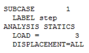
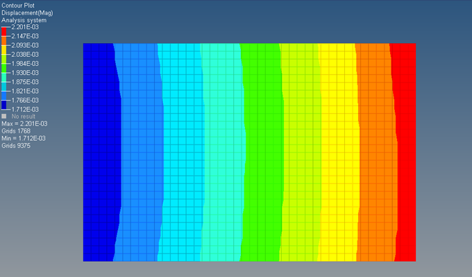
Figure 2: Displacement results of the Residual Structure (only).
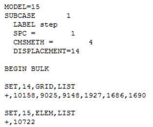
The following image illustrates the Displacement results of the Residual Structure and a set of grid points in the superelement after the end of the residual run. The generation run consists of MODEL data referencing element 10722 (SET 15) and the DISPLACEMENT entry references the grid points associated with element 10722 and some other grid points. You can see how only the results for the intersection of sets referenced by MODEL and the DISPLACEMENT entry is generated. The output data specified in the input decks is as follows:
Generation Run
Residual Run

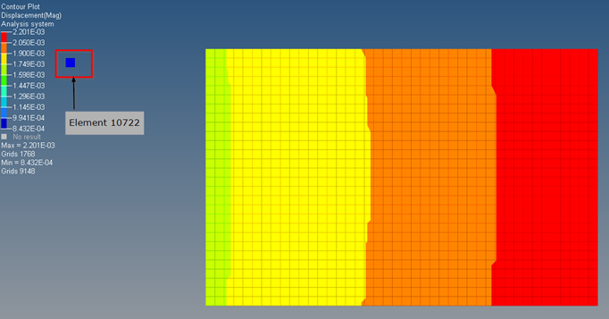
Figure 3: Displacement results of Residual Structure and element 10722 in the superelement.
Calculation of derived results (stress, and so on) for interior entities of superelements may be computationally intensive since the corresponding required data is calculated and stored during the generation run. Therefore, it is recommended to only request results for interior sections of the superelement that are critical for the current analysis.
See Also:
Theory: Superelements in Finite Element Analysis


