Summary
The aim of this example is to introduce /INIVOL for initial volume fractions of different materials in multi-material ALE elements, /SURF/PLANE for infinite plane, and fluid structure interaction (FSI) with a Lagrangian container.
Title
FSI and ALE container drop
|
|
Number
50
|
Brief Description
A container that is partially filled with liquid is dropped and the interaction between the liquid and structure can be studied. The liquid fill is defined using /INIVOL and infinite plane /SURF/PLANE. The contact between the structure and liquid is defined using /INTER/TYPE18.
|
Keywords
|
Input File
<install_directory>/demos/hwsolvers/radioss/50_invol_and_fluid_structure_interaction/fsi_drop_container*
|
Technical / Theoretical Level
Advanced
|
Overview
Description of the physical problem
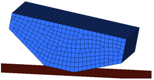
A container partially filled with water is simulated being dropped from a height of 1 meter. The container is partially filled with water with the remainder filled with air.
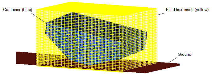
Fig 1: Problem description
Analysis, Assumptions and Modeling Description
Modeling description
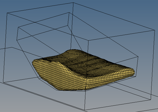
A hex mesh is created that fully encloses the structural container. The mesh size of the hex mesh should be ½ the size of the structural mesh. Ideally the hex mesh should also be ¼ of the structural mesh size in the direction of impact. To simplify this example, the hex mesh in this model does not adhere to the ¼ mesh size guideline.
Boundary conditions
Each outer side of the hex mesh is constrained to prevent displacement in the direction normal to the side. For example, the top and bottom of the hex mesh is constrained in the z translation DOF (Fig. 2). The same is done for the other four sides. The velocity at impact of a drop from 1 meter would be 4429 mm/s. Since the simulation is started right before impact, an initial velocity of 4429 mm/s is applied to the container and the fluid hex mesh (Fig. 2).
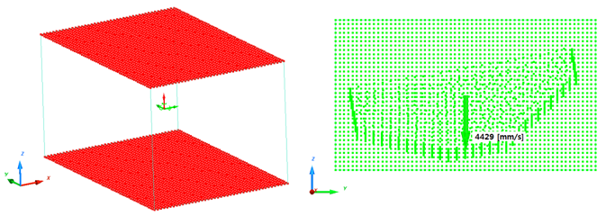
Fig 2: Boundary condition of container in z-direction
Units: mm, s, Mg, N, MPa
In one /MAT/LAW51 card, three different phases can be defined. The two phases are: Air and Water
Air is defined with the following characteristics:
| • | Reference density used in E.O.S (equation of state) = 1.2e-12 |
| • | Initial density of air = 1.2e-12 |
| • | Initial energy per unit volume = 0.25 |
| • | Hydrodynamic cavitation pressure = -1e-20 |
| • | Hydrodynamic coefficient C41 = 0.4 |
| • | Hydrodynamic coefficient C51 = 0.4 |
Water is defined with the following characteristics:
| • | Initial density of water = 1e-9 |
| • | Hydrodynamic cavitation pressure = -1e-20 |
| • | Hydrodynamic coefficient C03 = 0.10 |
| • | Hydrodynamic coefficient C13 = 2250 (Liquid bulk modulus) |
/ALE/MAT should also be defined for the /LAW/MAT51 material, to indicate that is an ALE model.
Coupled Euler-Lagrange (CEL) interface
To define the contact between the fluid and the structure a visco-elastic penalty formulation /INTER/TYPE18 interface is defined as follows:
Master is the Lagrange structure
Slave is the ALE fluid nodes
Gap is the Interface gap. The recommended value is 1.5 * fluid element size along the normal direction to contact
 is the (highest) fluid density
 is the velocity. as defined below:
| • | For incompressible models (ditching, sloshing, etc.), use the velocity of the event. |
| • | For compressible but not supersonic, use the speed of the sound in the material. |
| • | Compressible and transonic (Mach 0.8 to 1.0), replace the term v2 with v*c
where,  is the speed of the sound in the material and c is the speed of sound in air is the speed of the sound in the material and c is the speed of sound in air |
| • | Compressible and supersonic, use the velocity of the event |
| • | For an explosion, use the Chapman Jouguet velocity |
Sel is the surface area of the Lagrangian elements.
Gap is the interface gap, as defined above.
For this example:
Gap=1.5 * fluid element size = 1.5*2.5=3.75[mm]
Filling the container with /INIVOL
With /INIVOL, the water line can be defined in this part.
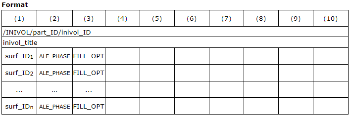
part_ID = Part ID of ALE hex mesh
surf_IDn = 3-nodes or 4-nodes surfaces only or /SURF/PLANE
ALE_PHASE = Phase of the multi-material ALE material
FILL_OPT = 0 or 1
=0: filling the side which along normal direction
=1: filling the side which against normal direction
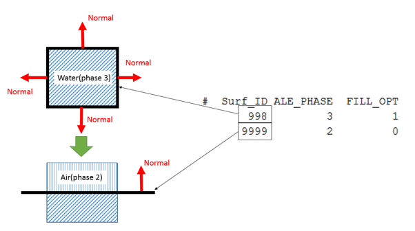
/INIVOL uses successive filling actions of the initial background multi-material ALE mesh, to get the final configuration of the initial volume fractions (three containers and three ALE phases). Initially the volume is filled by the first material defined in the /MAT/LAW51 field. In this case, the first material is air, so the entire hex mesh is first filled with air. Next, a surface is defined from the container part ID.
/SURF/PART/998
Vessel_Surf_Part
85
Since the surface normal of container part point outside, use FILL_OPT = 1 to fill the water (phase 3) inside the container (filling the side which against surface normal direction).
/INIVOL/86/10003507
INIVOL
# Surf_ID ALE_PHASE FILL_OPT
998 3 1
Now, ALE mesh is filled with ALE material 1 (air) from /MAT/LAW51 on the outside of the container and material 3 (water) inside the container. Lastly, define a surface plane, /SURF/PLANE to define the fill height. The normal of this plane points upward, use FILL_OPT = 0 to fill the air (phase 2) above the plane (filling the side along normal direction).
/INIVOL/86/10003507
# Surf_ID ALE_PHASE FILL_OPT
9999 2 0
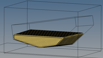
To check the initial fill, the following animation options can be used in the Engine file.
/ANIM/ELEM/DENSITY
/ANIM/ELEM/VFRAC
You can contour the model and use section cut to see inside, or use iso-surface, as shown in the image below.
/UPWIND - Anti-diffusive Technique
The amount of diffusion or mixing between the /MAT/LAW51 materials can be reduced by changing the third parameter, η3 in /UPWIND.
η3 = 1: Full Upwind (default value, recommended)
η3 = 1e-20: Less Upwind (less diffusive) => used in this example model.
η3 = 1e-30: Zero Upwind (less diffusive, but potentially unstable)
η3 = -1: Full Downwind (Anti-Diffusive Technique, potentially unstable)
/ALE/GRID/DONEA - ALE Grid Velocity
This activates the J. Donea Grid Formulation, where the velocity of a given grid node depends on velocity and displacements of neighboring grid nodes.
Engine Control
It is recommended to use time step scale factor 0.5 for ALE in /DT/BRICK in order to keep computation stable, and use fac=1.0 in /UPWM/SUPG. This option provides better velocity field in Cartesian grids when ALE material velocity is not normal to brick faces.
Simulation Results and Conclusions
To see the movement of the water in the container, and isosurface plot of results type, User Var 40 can be done. If the simple averaging method is used in HyperView, the results will look smoother, as shown below.
Also notice that water is starting to splash up the sides of the container at the end of the simulation.


